Friction apparatus

a technology of friction apparatus and braking distance, which is applied in the direction of heat treatment apparatus, furnaces, roads, etc., can solve the problems of increasing the braking distance, and achieve the effect of reducing the problem

Active Publication Date: 2018-05-31
KOREA RAILROAD RES INST
View PDF0 Cites 3 Cited by
  • Summary
  • Abstract
  • Description
  • Claims
  • Application Information

AI Technical Summary

Benefits of technology

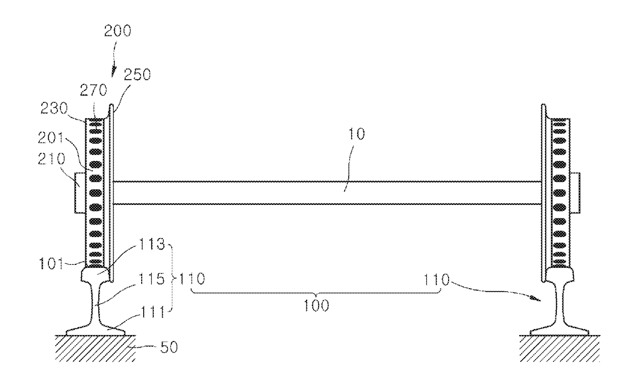
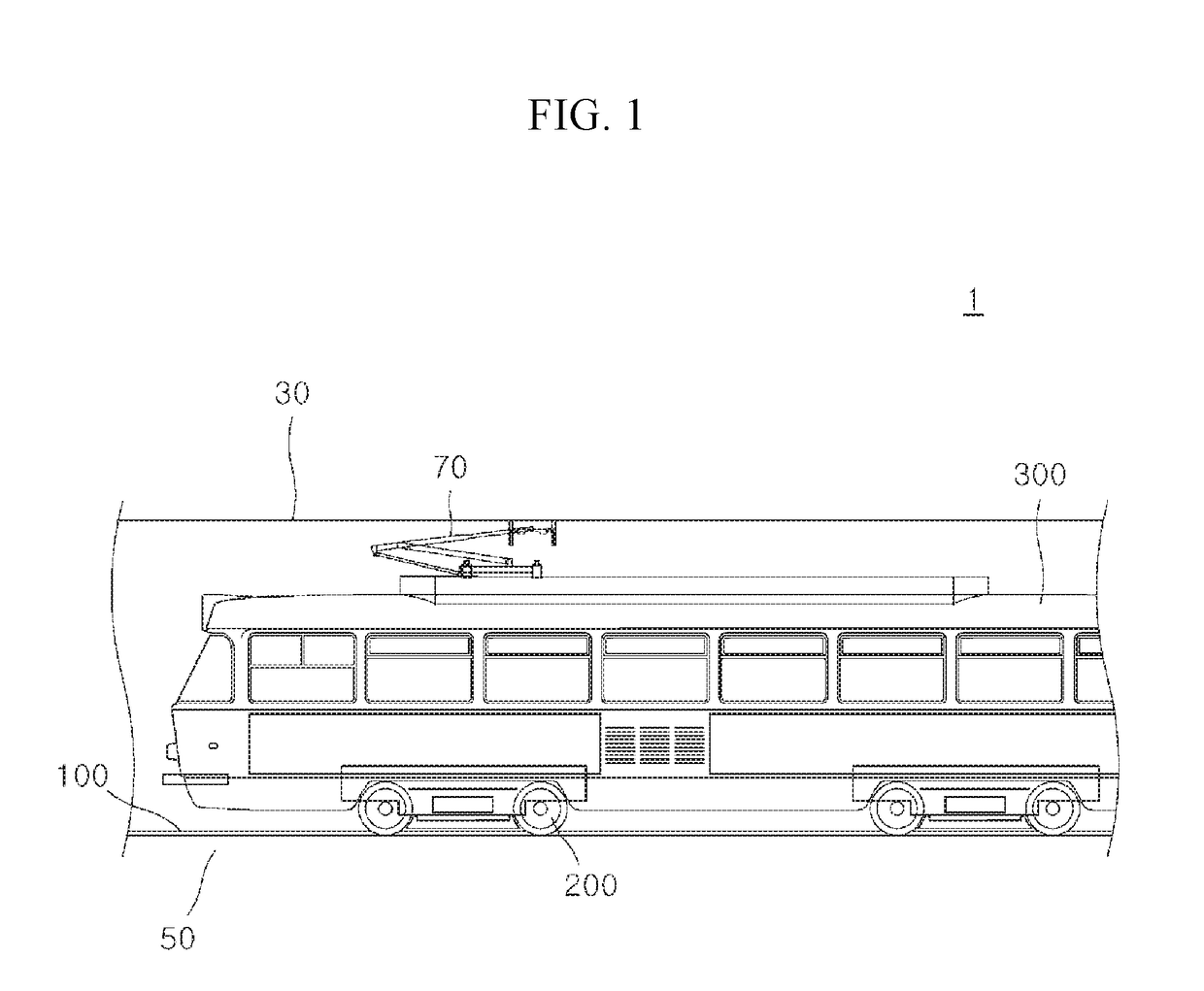
[0008]An aspect relates to a friction apparatus capable of simultaneously securing a braking distance, reducing slippage in an inclined section, and decreasing noise, wear, and friction energy of a railway vehicle and the like by improving adhesion between apparatuses configured to move relative to each other due to a frictional force.
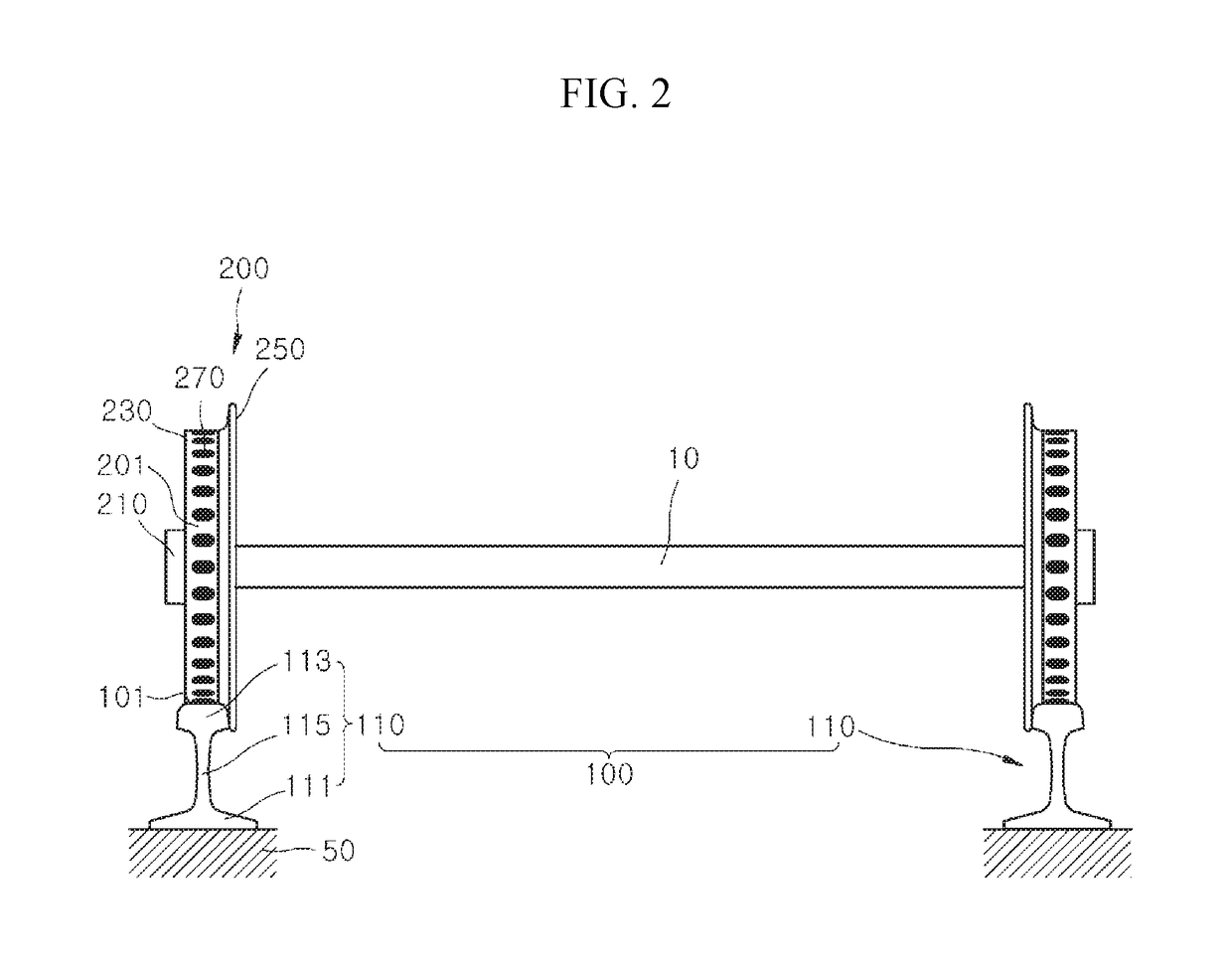
[0028]A friction apparatus according to embodiments of the present invention can control an adhesion coefficient and reduce generation of wear and noise of an apparatus by applying intermittently spaced hardened portions to a first member or a second member which are in contact with each other and move relative to each other.
[0030]Since an adhesion coefficient at a sufficient level is maintained even when a relative speed between a first member and a second member is high such as in sudden braking, a railway vehicle and the like can stably run on an inclined section, and accidents can be prevented by securing a braking force in the case of an emergency.
[0033]In embodiments of the present invention, since first hardened portions or second hardened portions are applied to the friction apparatus, a plastic flow of a rail portion or a second member which may occur due to sudden braking or acceleration can be suppressed, and thus a wear resistance and a fatigue resistance can be improved.
[0034]By letting a distance between a plurality of first hardened portions or between a plurality of second hardened portions be less than a longitudinal length of a region of a contact patch, rolling noises of a first member or a second member can be reduced due to the contact filter effect in which the noise is reduced in the case in which a size of an irregularity is smaller than the contact patch between the first member and the second member.
[0035]By letting a distance between central portions of adjacent first hardened portions or central portions of adjacent second hardened portions be greater than a longitudinal length of a contact patch of a rail member, which is a first member, and a wheel member, which is a second member, an adhesion coefficient between the rail member and the wheel member can be adjusted to a reduced range and be maintained to be a positive friction state in which a friction coefficient increases as a relative speed between the wheel member and a rail portion increases can be maintained, and thus noise, wear, and friction energy generated between the wheel member and the rail member can be reduced.

Problems solved by technology

Particularly, in the case in which the railway vehicle runs on a downwardly inclined section, slippage occurs, and thus there is a problem in that a braking distance is increased.
Conventionally, although a friction modifier has been applied to the wheel member and the rail portion such that the adhesion coefficient is within the predetermined range and the positive friction state is maintained, there have been problems in that the effect of the friction modifier is maintained only for a short period and an additional apparatus for applying the friction modifier has to be installed, and thus there is a need for reducing the problems.

Method used


Image

  • Friction apparatus
  • Friction apparatus
  • Friction apparatus

Examples


first embodiment

[0062]Referring to FIGS. 5 and 7, in a first embodiment, a distance d2 between the first hardened portions 117 may be less than a length d3 of a contact patch P, which is an instant contact area between the first member 100 and the second member 200.

[0063]In the case in which the distance d2 between the first hardened portions 117 is less than the length d3 of the contact patch P, a positive friction state in which an adhesion coefficient increases even when a slip ratio increases (see FIG. 7) is maintained.

[0064]In the case in which the distance d2 between the first hardened portions 117 is less than the length d3 of the contact patch P, which is the instant contact area between the first member 100 and the second member 200, since the adhesion coefficient is maintained in the positive friction state, noise and corrugation may be reduced, and a driving force or a braking force may be prevented from falling below a set value, and thus the railway vehicle may be prevented from slippi...

second embodiment

[0065]Referring to FIGS. 6 and 7, in a second embodiment, a distance d2 between first hardened portions 117 may be greater than a length d3 of a contact patch P, which is an instant contact area between a first member 100 and a second member 200.

[0066]In the case in which the distance d2 between the first hardened portions 117 is greater than the length d3 of the contact patch P, a positive friction state in which an adhesion coefficient increases as a slip ratio increases may be maintained, and a variation range of the adhesion coefficient may also decrease (see FIG. 7).

[0067]In the case in which the distance d2 between the first hardened portions 117 is greater than the length d3 of the contact patch P, which is the instant contact area between the first member 100 and the second member 200, since the adhesion coefficient is maintained in the positive friction state, noise and corrugation may be prevented, and a driving force or braking force is prevented from falling below a set ...


PUM

PropertyMeasurementUnit
frequencyaaaaaaaaaa
frequencyaaaaaaaaaa
distanceaaaaaaaaaa

Abstract

A friction apparatus is provided. The friction apparatus includes: a first member having a first surface; and a second member having a second surface that contacts the first surface, and moving while in contact with the first member, wherein at least one of the first surface and the second surface is hardened.

Description

CROSS-REFERENCE TO RELATED APPLICATIONS[0001]This application claims priority to PCT Application No. PCT / KR2016 / 005311 having a filing date of May 19, 2016, based off of Korean Patent Application No. 10-2015-0081898, having a filing date of Jun. 10, 2015, the entire contents of all which are hereby incorporated by reference.FIELD OF TECHNOLOGY[0002]The following relates to a friction apparatus, and more particularly, to a friction apparatus capable of decreasing a distance of braking between a first member and a second member and reducing noise, wear, and friction energy generated between the first member and the second member by improving adhesion between the first member and the second member which are in contact with each other and move relative to each other.BACKGROUND[0003]Generally, in apparatuses in which relative motion is performed by using a frictional force in a state in which a plurality of apparatuses, such as a wheel member of a railway vehicle and a rail portion of a ...

Claims


Application Information

Patent Timeline
Patent Type & Authority Applications(United States)
IPC IPC(8): E01B5/08B60B19/00B61H11/00B61C15/08
CPCE01B5/08B60B19/00B61H11/00B61C15/08B60B17/00B60B21/08E01B5/02C21D9/04C21D9/34C21D10/005C21D1/09C21D1/10Y02P10/25
Inventor CHO, YONG HYEONCHOI, JIN YUKANG, YUN SUKKIM, JOO UK
Owner KOREA RAILROAD RES INST
Why Eureka
Try Eureka