Unlock instant, AI-driven research and patent intelligence for your innovation.

Automatic machining force optimizing system and method for nc program

a technology of automatic machining force and optimization system, applied in the field of system and a method for optimizing machining force for nc program, can solve the problems of difficult to obtain the actual tool path, scientific methods, and difficulty in determining the path of the tool

Active Publication Date: 2018-05-31
IND TECH RES INST
View PDF8 Cites 14 Cited by
  • Summary
  • Abstract
  • Description
  • Claims
  • Application Information

AI Technical Summary

Benefits of technology

The patent text describes an automatic machining force optimizing system for a computer-controlled machine tool. This system includes a tool path acquisition unit and aNC program optimizing unit. The system automatically acquires the coordinate information of the machine tool, performs modifications to the coordinate information to create a tool path, and then analyzes the machining force to modify the processing feed rate in real-time, resulting in an optimizedNC program that can improve the efficiency and accuracy of machining processes. The technical effects of this system may include improved productivity, reduced costs, and improved accuracy of machining processes.

Problems solved by technology

Therefore, how to select appropriate machining conditions to improve production capacity has been the key issue of this industry.
However, since the NC program (G code) including the macroinstruction defined by different controllers mostly can not accurately express the geometric structure or contour of the workpiece, and the extent of support of the above-mentioned processing aided software system with respect to “that the existing NC program is interpreted as tool path” is insufficient too, thereby, it is difficult to obtain the actual tool path, therefore, it is not easy to perform the diagnosis of tool path.
As the engineers are lack of scientific methods to adjust the machining conditions, all they can do is to adjust through their experience.
In order to lower the processing time, a relatively excessive machining condition is mostly used which results in tool damage or even breaking and consequently causes workpiece's wearing and cost rising, or a relatively conservative machining conditions is used which results in poor processing efficiency.

Method used


Image

  • Automatic machining force optimizing system and method for nc program
  • Automatic machining force optimizing system and method for nc program
  • Automatic machining force optimizing system and method for nc program

Examples


Embodiment Construction

[0033]The following descriptions are embodiments of the disclosure employing some particular concrete examples. Those people skilled in the art are capable of easily realizing the advantages and efficacies of the disclosure through the content disclosed by the patent specification of the disclosure.

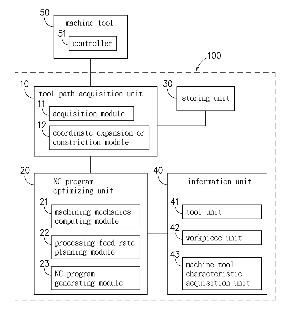
[0034]FIG. 2 is a block diagram of the system to optimize machining force for NC program showing the mechanism of the embodiment of the disclosure, As shown in FIG. 2, the system to optimize machining force for NC program of the disclosure includes a tool path acquisition unit 10 and a NC program optimizing unit 20. The automatic NC program machining force optimizing system 100 is connected to the controller 51 which is used to perform a NC program, and the controller 51 drives the tool in accordance with the NC program to control the machine tool 50 to perform processing with respect to the workpiece.

[0035]The tool path acquisition unit 10 is employed to acquire the coordinate informatio...


PUM


Abstract

A system and a method for optimizing machining force of NC program is disclosed. The system includes a tool path acquisition unit and a NC program optimizing unit; the tool path acquisition unit is for acquiring a coordinate set of points composed by a coordinate information outputted by a controller, and modifying with respect to the coordinate set of points so as to form a tool path; the NC program optimizing unit is for analyzing machining force in accordance with the tool path, a tool information, a workpiece information and a machine tool characteristic information, and modifying with modified processing feed rates to generate an optimized NC program.

Description

CROSS REFERENCE TO RELATED APPLICATION[0001]This application also claims priority to Taiwan Patent Application No. 105139298 filed in the Taiwan Patent Office on Nov. 29, 2016, the entire content of which is incorporated herein by reference.BACKGROUND OF THE DISCLOSURE1. Field of the Disclosure[0002]The disclosure relates to a system and a method for optimizing machining force for NC program, and more particularly, to a system and a method for optimizing machining force for NC program that a coordinate set of points is formed by connecting to a machine tool's controller and acquiring coordinate information outputted by the controller, then to aim at the coordinate set of points to perform coordinate expansion or constriction so as to form a tool path, and then undertake the cutting mechanics analysis and optimization to improve the process efficiency, in the meantime, to resolve the tool damage problem caused by excessive tool machining force.2. Description of the Prior Art[0003]Pro...

Claims


Application Information

Patent Timeline
Patent Type & Authority Applications(United States)
IPC IPC(8): G05B19/4093
CPCG05B2219/36489G05B19/40937G05B19/4155Y02P90/02
Inventor HSU, CHIH-YUANCHANG, YU-LINGTSENG, YU-ANLIANG, SHUO-PENGLUO, TZUO-LIANG
Owner IND TECH RES INST
Features
  • R&D
  • Intellectual Property
  • Life Sciences
  • Materials
  • Tech Scout
  • Unparalleled Data Quality
  • Higher Quality Content
  • 60% Fewer Hallucinations
Learn More