
Pneumatic tire

a technology of pneumatic tires and tires, applied in special tyres, rolling resistance optimization, transportation and packaging, etc., can solve the problems of reducing the cured stiffness of such tread rubber compositions, and difficult to improve the wear characteristics of tires without sacrificing wet skid resistance and traction characteristics

Inactive Publication Date: 2018-06-07
THE GOODYEAR TIRE & RUBBER CO
View PDF4 Cites 7 Cited by
  • Summary
  • Abstract
  • Description
  • Claims
  • Application Information

AI Technical Summary

Benefits of technology

The patent describes a rubber composition that has been formulated using different compounds. These compounds have been mixed together with standard amounts of additives such as curatives, coupling agents, and antidegradants. The technical effect of this invention is that it provides a rubber composition that has improved properties and performance in various applications.

Problems solved by technology

It has traditionally been very difficult to improve a tire's wear characteristics without sacrificing its wet skid resistance and traction characteristics.
Here, the challenge is to reduce the cured stiffness of such tread rubber compositions, as indicated by having a lower storage modulus G′ at −20° C., when the tread is intended to be used for low temperature winter conditions, particularly for vehicular snow driving.
It is considered that significant challenges are presented for providing such tire tread rubber compositions for maintaining both their wet traction while promoting low temperature (e.g. winter) performance.

Method used


Image

  • Pneumatic tire
  • Pneumatic tire
  • Pneumatic tire

Examples


example 1

[0088]This example illustrates the advantage of a rubber composition according to the invention. Rubber compounds were mixed according to the formulations shown in Table 1, with amounts given in phr. Compounds also containing standard amounts of additives including curatives, coupling agents, and antidegradants.

[0089]The compounds were cured and tested for physical properties as shown in Table 2.

TABLE 1Composition TypeInner TreadLateralCentralSBR low Tg s-SBR1757575BR high cis2252525Silica 125 m2 / g397118118Silane coupling agent46.17.47.4TDAE oil201826Resin504734Fatty acid65.05.05.0Waxes1.51.51.5Antioxidants73.03.03.0ZnO1.21.51.5Sulfur0.370.60.57Accelerators84.556.16.01Solution polymerized SBR with styrene content of 15% and 1,2-vinyl content of 30%, Tg = −60° C., as SLR3402 from Styron.2High cis 1,4-polybutadiene rubber as Budene1229 ™ from The Goodyear Tire & Rubber Company having a Tg of about −106° C. having a vinyl 1,2-content of less than about 4 percent and a cis 1,4-content o...


PUM

PropertyMeasurementUnit
Temperatureaaaaaaaaaa

Abstract

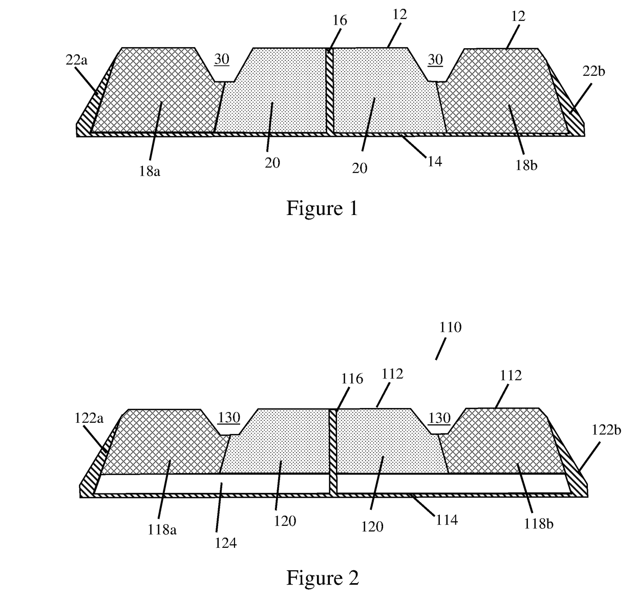
The present invention is directed to pneumatic tire having a tread comprising a tread base layer and an outer cap layer disposed radially outward of the base layer, the outer cap layer comprising an axially central zone and two lateral zones each disposed axially adjacent to the central zone; the central zone comprising a central zone composition and lateral zones each comprising a lateral zone composition; the central zone composition and the lateral zone composition each comprising, based on 100 parts by weight of elastomer (phr), from about 50 to about 90 phr of a solution polymerized styrene-butadiene rubber having a glass transition temperature (Tg) ranging from −65° C. to −55° C. and functionalized with an alkoxysilane group and at least one functional group selected from the group consisting of primary amines and thiols; from about 50 to about 10 phr of polybutadiene having a cis 1,4 content greater than 95 percent and a Tg ranging from −80 to −110° C.; from 100 to 180 phr of precipitated silica; and from 30 to 80 phr of a combination of a resin having a Tg of at least 30° C. and an oil wherein the weight ratio of the amount of silica to the total amount of resin and oil is less than 3; wherein the weight ratio of resin to oil in one of the central zone composition and lateral zone composition is greater than 2, and the weight ratio of resin to oil in the other of the central zone composition and lateral zone composition is less than 2.

Description

BACKGROUND OF THE INVENTION[0001]It is highly desirable for tires to have good wet skid resistance, low rolling resistance, and good wear characteristics. It has traditionally been very difficult to improve a tire's wear characteristics without sacrificing its wet skid resistance and traction characteristics. These properties depend, to a great extent, on the dynamic viscoelastic properties of the rubbers utilized in making the tire.[0002]In order to reduce the rolling resistance and to improve the treadwear characteristics of tires, rubbers having a high rebound have traditionally been utilized in making tire tread rubber compounds. On the other hand, in order to increase the wet skid resistance of a tire, rubbers which undergo a large energy loss have generally been utilized in the tire's tread. In order to balance these two viscoelastically inconsistent properties, mixtures of various types of synthetic and natural rubber are normally utilized in tire treads.[0003]Tires are somet...

Claims


Application Information

Patent Timeline
IPC IPC(8): B60C11/00B60C1/00
CPCB60C1/0016B60C11/0066C08L9/06C08K2003/2296C08L2205/035C08L9/00C08L91/00C08K13/06C08K9/06C08K3/36C08K5/09C08K3/22C08K3/06C08L25/08C08L15/00B60C11/0058B60C2011/016Y02T10/86C08L25/16C08L91/06C08K5/548C08K5/18C08K5/47C08L19/006C08L47/00B60C2011/0016
Inventor ISITMAN, NIHAT ALISTEINER, PASCAL PATRICKCHAIDRON, MARIE CHARLOTTETHIELEN, GEORGES MARCEL VICTOR
Owner THE GOODYEAR TIRE & RUBBER CO
Learn More