Projection type display device, projection display method, and projection display program

a display device and projection display technology, applied in static indicating devices, instruments, transportation and packaging, etc., can solve the problems of increasing the manufacturing cost of huds and the vehicle on which huds are mounted, and the difficulty of only using optical systems to correct distortion, etc., and achieve the effect of easy variation

Active Publication Date: 2018-06-07
FUJIFILM CORP
View PDF1 Cites 18 Cited by
  • Summary
  • Abstract
  • Description
  • Claims
  • Application Information

AI Technical Summary

Benefits of technology

[0006]A windshield of a vehicle has been designed in preferential consideration of design or the like compared with an optical

Problems solved by technology

Thus, the manufacturing cost of the HUD and a vehicle on which the HUD is mounted increases.
Further, in a case where a projection range of image light b

Method used


Image

  • Projection type display device, projection display method, and projection display program
  • Projection type display device, projection display method, and projection display program
  • Projection type display device, projection display method, and projection display program

Examples


first modification example

[0086]FIG. 4 is a block diagram showing an internal configuration of a system controller 60A that is a modification example of the system controller 60 shown in FIG. 2. The system controller 60A of FIG. 4 has the same configuration as that of the system controller 60 in FIG. 3 except that the functions of the measurement data acquisition unit 61 and the correction data generation unit 62 are partially different therefrom. Accordingly, only parts that are different from those in FIG. 3 will be described.

[0087]In a case where the correction data generation unit 62 of the system controller 60A generates correction data using the above-described method, the correction data generation unit 62 stores the correction data in the ROM of the storage unit 30 in association with the direction of a line of sight used for generation of the correction data.

[0088]In a case where there is a change in the line of sight detected by the sight line detection unit 70, the correction data generation unit ...

second modification example

[0093]FIG. 5 is a block diagram showing an internal configuration of a system controller 60B that is a modification example of the system controller 60 shown in FIG. 2. The system controller 60B in FIG. 5 has the same configuration as that of the system controller 60 in FIG. 3 except for a function of the measurement data acquisition unit 61 is partially different therefrom. Accordingly, only parts that are different from those in FIG. 3 will be described.

[0094]When the projection display system is started, the measurement data acquisition unit 61 of the system controller 60B acquires measurement data on a three-dimensional shape of the entirety of the projectable range 1A of the windshield 1 from the windshield shape measurement device 8, and stores the result in the ROM of the storage unit 30. The storage unit 30 in the second modification example forms a measurement data storage unit.

[0095]Further, the measurement data acquisition unit 61 of the system controller 60B extracts mea...

third modification example

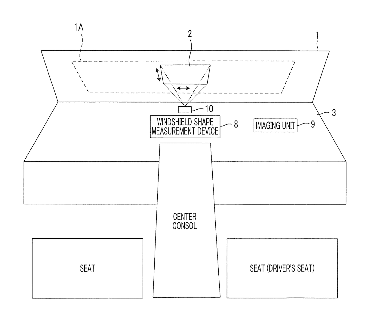
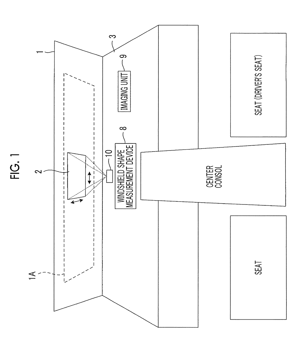
[0102]In the HUD 10 of FIG. 1, by making a projection range of image light movable by the driving mechanism 20, it is possible to display a virtual image over a wide range.

[0103]As the modification example, the projection unit 50 that is optically designed to be capable of projecting image light onto the entirety of the projectable range 1A may be used. In this modification example, as a measurement data acquisition region, for example, a region of a size of the same degree as that of a central visual field of a driver may be set.

[0104]That is, the system controller 60 generates correction data on the basis of measurement data on a three-dimensional shape of a part (a range corresponding to the central visual field of the driver) in the projectable range 1A in which image light is projected, and the direction of the line of sight of the driver, and corrects a portion corresponding to the measurement data acquisition region in image data that is a source of image light to be projecte...


PUM


Abstract

An HUD includes a projection unit that projects image light that is spatially modulated on the basis of image data onto a windshield, a sight line detection unit that detects a line of sight of a driver of a vehicle, and a system controller that acquires measurement data on shape of a region including a point that intersects the line of sight of the driver in a projectable range of the image light in the windshield, generates correction data for correcting distortion of an image based on the image light projected onto the region on the basis of the acquired measurement data and the direction of the line of sight of the driver, and corrects the image data using the generated correction data.

Description

CROSS-REFERENCE TO RELATED APPLICATIONS[0001]This application is a Continuation of PCT International Application No. PCT / JP2016 / 069398 filed on Jun. 30, 2016, which claims priority under 35 U.S.C § 119(a) to Japanese Patent Application No. 2015-167018 filed on Aug. 26, 2015. Each of the above application(s) is hereby expressly incorporated by reference, in its entirety, into the present application.BACKGROUND OF THE INVENTION1. Field of the Invention[0002]The present invention relates to a projection type display device, a projection display method, and a non-transitory computer readable recording medium storing a projection display program.2. Description of the Related Art[0003]A head-up display (HUD) for a vehicle that uses a windshield of a vehicle such as an automobile, a train, a heavy machine, a construction machine, an aircraft, a ship, or an agricultural machine as a screen and projects image light onto the screen to cause a driver to visually recognize a virtual image based...

Claims


Application Information

Patent Timeline
IPC IPC(8): G02B27/01G03B21/00G02B27/09G06K9/00
CPCG02B27/01G03B21/005G02B27/0938G06K9/00671G02B2027/0181G02B2027/014B60K35/00G09G5/38G09G3/001G09G2320/0693G09G2354/00G09G2380/10H04N9/3147H04N9/3185H04N9/3194B60K2370/12B60K2370/15B60K2370/334B60K2370/149B60K2370/1529B60K2370/785G06V20/20G06V20/597
Inventor FUJITA, KOUDAI
Owner FUJIFILM CORP
Why Eureka
Try Eureka