
Illumination system and projection apparatus using the same

Active Publication Date: 2018-06-07
CORETRONIC
View PDF2 Cites 13 Cited by
  • Summary
  • Abstract
  • Description
  • Claims
  • Application Information

AI Technical Summary

Benefits of technology

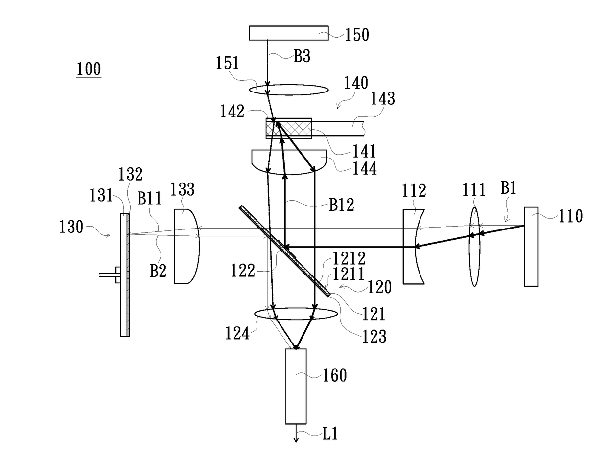
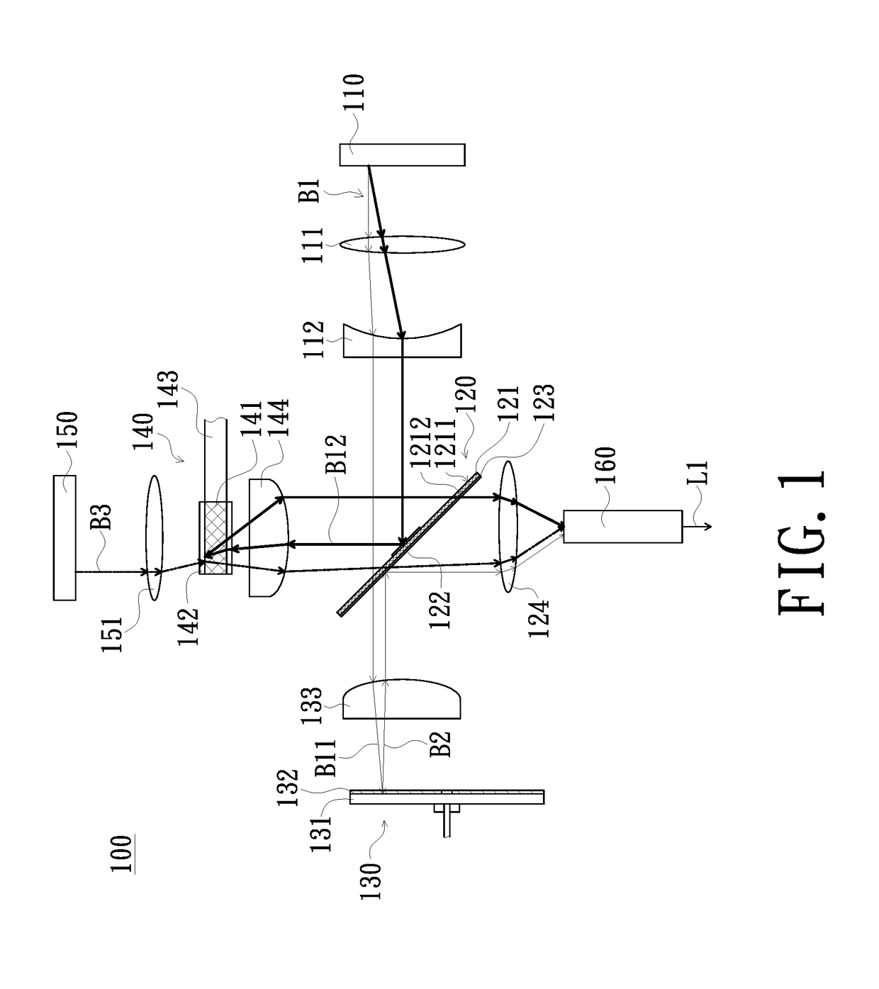
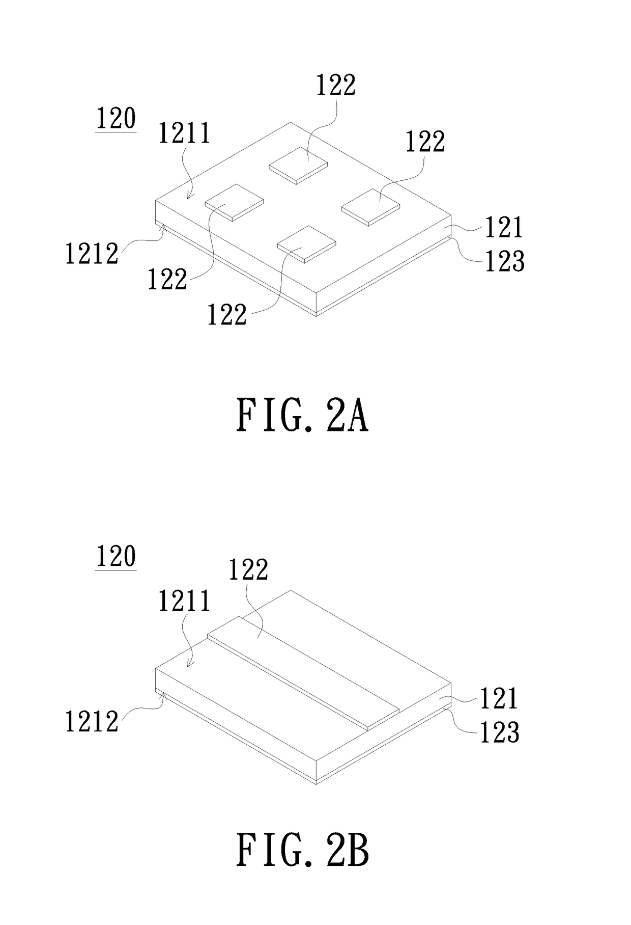
The invention provides an illumination system and a projection apparatus that can reduce the cost and complexity of the traditional systems. The illumination system separates a color beam into two sub-beams using a beam-splitting element and converts one of them using an optical wavelength converting element, resulting in a cost reduction and a reduction in the number of laser sources needed. The projection apparatus simplifies the light transmission path and reduces the size of the system. The first and second light sources shared the beam-splitting element, further reducing the volume of the system. Additionally, a moving member may improve the quality of the projection by reducing speckle.

Problems solved by technology

However, due to the known laser projection apparatus with three light valves requires two sets of blue laser sources, so the cost is high.
In addition, due to the optical path design is complicated, so the volume is large.

Method used


Image

  • Illumination system and projection apparatus using the same
  • Illumination system and projection apparatus using the same
  • Illumination system and projection apparatus using the same

Examples


Embodiment Construction

[0026]In the following detailed description of the preferred embodiments, reference is made to the accompanying drawings which form a part hereof, and in which is shown by way of illustration specific embodiments in which the invention may be practiced. In this regard, directional terminology, such as “top”, “bottom”, “front”, “back”, etc., is used with reference to the orientation of the Figure(s) being described. The components of the invention can be positioned in a number of different orientations. As such, the directional terminology is used for purposes of illustration and is in no way limiting. On the other hand, the drawings are only schematic and the sizes of components may be exaggerated for clarity. It is to be understood that other embodiments may be utilized and structural changes may be made without departing from the scope of the invention. Also, it is to be understood that the phraseology and terminology used herein are for the purpose of description and should not b...


PUM


Abstract

An illumination system includes a first light source providing a first color beam, a first beam-splitting element which disposes on a transmission path of the first color beam and separates the first color beam into a first sub-beam and a second sub-beam, an optical wavelength conversion element which receives the first sub-beam and converts the first sub-beam into a second color beam and reflects the second color beam back to the first beam-splitting element, a second light source providing a third color beam, and a second beam-splitting element which is located between the second light source and the first beam-splitting element to reflect the second sub-beam. The third color beam passes through the second beam-splitting element and is transmitted to the first beam-splitting element. The second sub-beam, the second color beam and the third color beam are combined into an illumination beam.

Description

CROSS-REFERENCE TO RELATED APPLICATION[0001]This application claims the priority benefit of CN201611094953.4 filed on 2016 Dec. 2. The entirety of the above-mentioned patent application is hereby incorporated by reference herein and made a part of this specification.FIELD OF THE INVENTION[0002]The invention relates to a light source module, and more particularly to an illumination system and a projection apparatus using the same.BACKGROUND OF THE INVENTION[0003]The share of laser projection apparatus adopting laser source in the market of high-end projection apparatus is getting higher and higher. In general, one of the high-end projection apparatuses is referred to a projection apparatus with three light valves, and therefore, it is necessary to provide three continuous color beams (red, green, blue) to the three light valves respectively.[0004]A known laser projection apparatus with three light valves generally includes two sets of blue laser sources. One of the two sets of blue l...

Claims


Application Information

Patent Timeline
IPC IPC(8): G02B27/10G03B21/20G02B27/28
CPCG02B27/10G03B21/2066G03B21/204G02B27/283G02B27/1006H04N9/3164H04N9/3158
Inventor LIAO, CHIEN-CHUNGCHANG, JUI
Owner CORETRONIC
Learn More