Liquid crystal panel and liquid crystal display device

a liquid crystal display and panel technology, applied in the direction of identification means, instruments, polarising elements, etc., can solve the problem of uneven display surfa

Active Publication Date: 2018-06-07
FUJIFILM CORP
View PDF8 Cites 10 Cited by
  • Summary
  • Abstract
  • Description
  • Claims
  • Application Information

AI Technical Summary

Benefits of technology

[0046]According to one aspect of the present invention, it is possible to provide a liquid crystal panel including a polarizing plate having a front-surface plate including at least a resin film, and a front-side polarizing plate, bonded via an adhesive layer, in whi...

Problems solved by technology

However, as a result of extensive studies conducted by the present inventors, it became apparent that in a case where a liquid crystal panel is configured by bonding a front-surface plate including a resin film instead of glass with a front-side polarizing plate via an adhesive layer, a liquid crystal display device inc...

Method used


Image

  • Liquid crystal panel and liquid crystal display device
  • Liquid crystal panel and liquid crystal display device
  • Liquid crystal panel and liquid crystal display device

Examples


examples

[0310]Hereinafter, the present invention will be described in more detail with reference to Examples. The materials, reagents, the amounts and ratios of the materials, operations, and the like shown in the following Examples can be appropriately changed within a scope that does not depart from the gist of the present invention. Accordingly, the scope of the present invention is not limited to the following specific examples. In the following description, “%” means “% by mass” unless otherwise specified. The steps described below are carried out at room temperature unless otherwise specified. Here, the room temperature refers to a temperature in a range of 20° C. to 25° C.

[0311][Manufacture of Front-Surface Plate]

[0312]

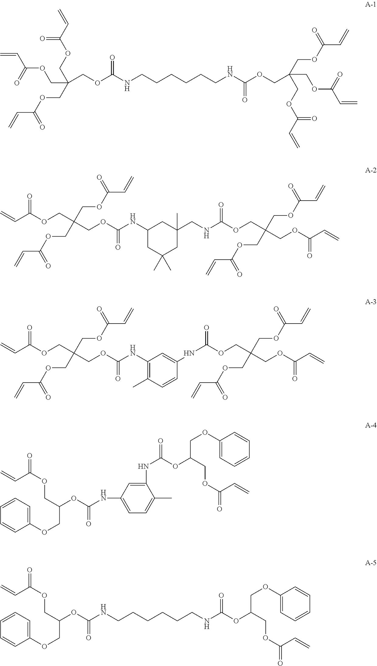
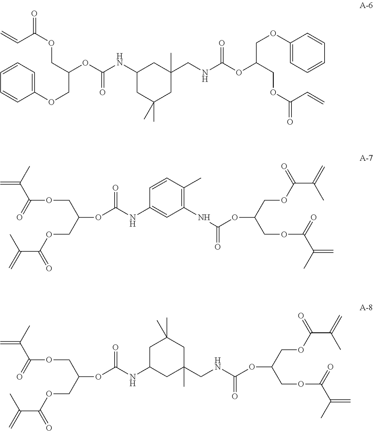
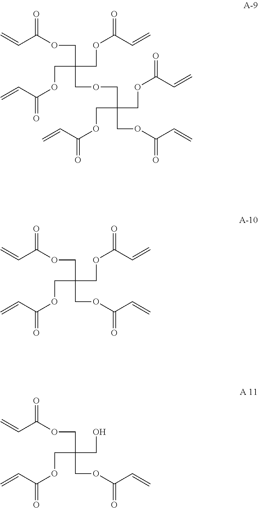
[0313]The respective components were added based on the compositions shown in Table 1, and filtration was carried out using a polypropylene-made filter having a pore diameter of 10 μm to prepare actinic energy ray-curable compositions HC1 to HC5. With regard to the com...


PUM


Abstract

The liquid crystal panel has a front-surface plate, a front-side polarizing plate, a liquid crystal display element, and a rear-side polarizing plate in an integrally laminated state, in which the front-surface plate and the front-side polarizing plate are in the state of being laminated with each other via an adhesive layer having a thickness of 2 μm or more, and the liquid crystal panel satisfies Formula A-1: 2020>ECp×dCp×εCp×(100−P)+(Ef×df×εf)−(Er×dr×εr)>0 (ECp is the modulus of elasticity, dCp is the thickness, and εCp is the humidity dimensional change rate, of the front-surface plate, Ef is the modulus of elasticity, df is the thickness, and εf is the humidity dimensional change rate, of the front-side polarizing plate, Er is the modulus of elasticity, dr is the thickness, and εr is the humidity dimensional change rate, of the rear-side polarizing plate, P is the stress relaxation rate of the adhesive layer).

Description

CROSS-REFERENCE TO RELATED APPLICATIONS[0001]This application is a Continuation of PCT International Application No. PCT / JP2016 / 71225 filed on Jul. 20, 2016, which claims priority under 35 U.S.C. § 119(a) to Japanese Patent Application No. 2015-144446 filed on Jul. 21, 2015. Each of the above applications is hereby expressly incorporated by reference, in its entirety, into the present application.BACKGROUND OF THE INVENTION1. Field of the Invention[0002]The present invention relates to a liquid crystal panel, and a liquid crystal display device including the liquid crystal panel.2. Description of the Related Art[0003]A liquid crystal display device includes a liquid crystal panel and a backlight unit. Further, the liquid crystal panel is usually configured such that a front-surface plate, a polarizing plate, a liquid crystal display element, and a polarizing plate are disposed in the direction from the viewing side to the backlight unit side. Hereinafter, out of two polarizing plate...

Claims


Application Information

Patent Timeline
IPC IPC(8): G02F1/1335G02F1/1333G06F3/041
CPCG02F1/133528G02F1/133602G02F1/13338G06F3/0412G02B5/3033G02F1/133305G02F2202/28G02F1/133331G02F1/133562G02B5/30G02F1/1335G09F9/00
Inventor UEKI, KEIGOTAKADA, KATSUYUKI
Owner FUJIFILM CORP
Why Eureka
Try Eureka