Scanner vis

a scanning and vising technology, applied in the field of scanning instruments, can solve the problem that the completeness cannot be guaranteed, and achieve the effect of enhancing the quality of the image, and ensuring the completeness

Active Publication Date: 2018-06-07
HEXAGON TECH CENT GMBH
View PDF2 Cites 40 Cited by
  • Summary
  • Abstract
  • Description
  • Claims
  • Application Information

AI Technical Summary

Benefits of technology

[0079]In an embodiment of the method according to the invention, registering is performed additionally based on a global optimisation, in particular wherein the global optimisation may be performed one or more times until convergence is reached according to a given criterion. The global optimisation may comprise a bundle-adjustment (BA) that jointly minimises 2D-to-2D distances between 2D reprojections of the first image data, and at least one of: 2D-to-3D distances between 2D reprojections of the first initial image data and 3D points of the first 3D point cloud, and 2D-to-3D distances between 2D reprojections of the first final image dat...

Problems solved by technology

It does not, howeve...

Method used


Image

  • Scanner vis
  • Scanner vis
  • Scanner vis

Examples


Embodiment Construction

[0097]Trajectory and Environment Reconstruction

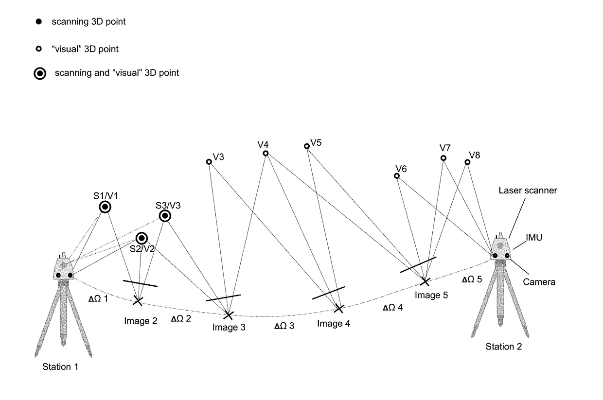
[0098]FIG. 1 shows one embodiment of the method according to the invention. The trajectory of the laser scanner while being transported from station 1 to station 2 is estimated from additional sensor configurations on the laser scanner, such as one or more cameras, gyroscopes and / or accelerometers. The gyroscope measures the angular rate and the accelerometer measures the accelerations of the laser scanner during movement. These sensors are proprioceptive and drift prone. The cameras are exteroceptive sensors, which can reduce drift. The cameras are measuring the angular displacement. These sensor modalities are combined in a stochastic filtering or a non-linear optimisation framework to estimate the pose of the laser scanner and the scene structure at specific time steps during the displacement. The sequence of poses constitutes the laser scanner trajectory, and the consecutive scene structure constitutes the reconstructed environmen...


PUM


Abstract

A method for registering two or more three-dimensional (3D) point clouds. The method includes, with a surveying instrument, obtaining a first 3D point cloud of a first setting at a first position, initiating a first Simultaneous Localisation and Mapping (SLAM) process by capturing first initial image data at the first position with a camera unit comprised by the surveying instrument, wherein the first initial image data and the first 3D point cloud share a first overlap, finalising the first SLAM process at the second position by capturing first final image data with the camera unit, wherein the first final image data are comprised by the first image data, with the surveying instrument, obtaining a second 3D point cloud of a second setting at the second position, and based on the first SLAM process, registering the first 3D point cloud and the second 3D point cloud relative to each other.

Description

CROSS-REFERENCE TO RELATED APPLICATIONS[0001]This application claims priority to European Patent Application No. 1602711.4 filed on Dec. 7, 2016. The foregoing patent application are incorporated herein by reference.FIELD OF INVENTION[0002]The present invention relates generally to a surveying instrument and more particularly to registering two or more three-dimensional (3D) point clouds using a surveying instrument.BACKGROUND[0003]Laser scanning is used to survey many different settings such as construction sites, historical buildings, industrial facilities or any other applicable setting. Such sceneries (settings) are commonly surveyed with 3D laser scanners with use of the time-of-flight (TOF) measuring method in order to sample a cloud of 3D points within a coordinate system. Additionally, a camera may be associated with a laser scanner and may be configured to capture images associated with the setting being scanned.[0004]An exemplary workflow with a laser scanner comprises sca...

Claims


Application Information

Patent Timeline
IPC IPC(8): G06T7/33G06T7/38G01C15/00G01B11/00H04N5/232
CPCG06T7/337G06T7/38G01C15/002G01B11/005H04N5/23238G06T2207/10028G06T2207/10016G06T7/33G06T2207/10021G01C1/04G01C15/00G06T7/579G06T2207/30241G06T2207/30244G06T7/30G06T7/277H04N23/698
Inventor METZLER, BERNHARDVELIZHEV, ALEXANDERGACHTER TOYA, STEFAN MARTIN BENJAMIN
Owner HEXAGON TECH CENT GMBH
Why Eureka
Try Eureka