Method for calibrating an imaging device and an imaging device

a technology of imaging device and calibration method, applied in the field of computer vision technology, can solve the problems of inability to accurately calibrate imaging devices, failure of calibration or unacceptable precision, user may have to spend extra time and effort in learning, etc., to improve the operability and reduce the difficulty

Inactive Publication Date: 2018-06-07
SZ DJI TECH CO LTD
View PDF0 Cites 2 Cited by
  • Summary
  • Abstract
  • Description
  • Claims
  • Application Information

AI Technical Summary

Benefits of technology

[0031]It will be appreciated that, the technical solutions of the present disclosure are advantageous in various aspects. When a user is calibrating an imaging device, a first attitude information of the imaging device relative to a screen can be calculated from a first set of images captured by the imaging device, a first calibration signal can be generated from the first attitude information and displayed on a checkerboard on the screen, and a guiding signal can be displayed on the screen, such that the user can simply move the imaging device in accordance with the guiding signal. Therefore, a user having no related experience and theory can move a position of the imaging device or the screen in accordance with the calibration signal and the guiding signal, reducing a difficulty and improving an operability in calibrating the imaging device.

Problems solved by technology

However, the existing imaging device calibration requires a certain level of theoretical knowledge from the technician.
The technician moves the checkerboard based on his / her experience and theory, and an improper movement of the checkerboard can lead to a failure in calibration or an unacceptable precision.
Therefore, an ordinary user having no related experience or theory may not perform the calibration process alone, and the user may have to spend extra time and effort in learning and practicing the imaging device calibration.

Method used


Image

  • Method for calibrating an imaging device and an imaging device
  • Method for calibrating an imaging device and an imaging device
  • Method for calibrating an imaging device and an imaging device

Examples


Embodiment Construction

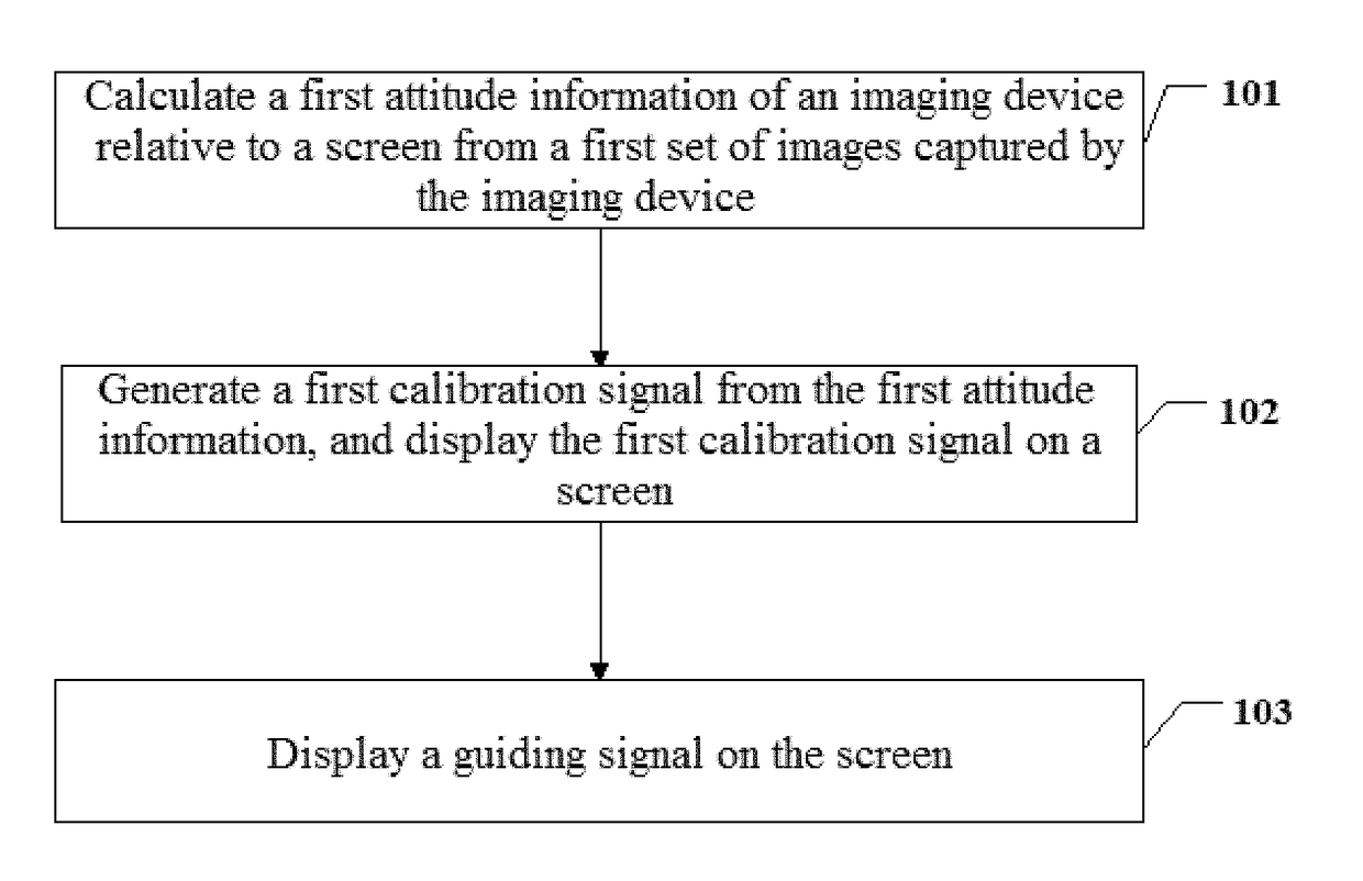
[0040]Embodiments of the disclosure provide a method and an apparatus for calibrating an imaging device. A calibration signal and a guiding signal can be displayed on a screen in calibrating the imaging device, enabling a user having no related experience and theory to move the imaging device or the screen based upon the calibration signal and the guiding signal, such that a difficulty in calibrating the imaging device can be reduced.

[0041]A better understanding of the disclosure will be obtained by reference to the following detailed description that sets forth illustrative embodiments with reference to the drawings. It will be apparent that, the embodiments described herein are merely provided by way of example. Those skilled in the art can conceive various embodiments in light of those disclosed herein without inventive efforts, and all these embodiments are within the scope of the disclosure.

[0042]A detailed description of the disclosure will be provided with reference to variou...


PUM


Abstract

A method for calibrating an imaging device includes calculating attitude information of the imaging device relative to a screen based at least in part on an image captured by the imaging device. The image includes information of at least a portion of a checkerboard displayed on the screen. The method further includes generating a calibration signal based at least in part on the attitude information, displaying the calibration signal on the checkerboard on the screen, and displaying a guiding signal on the screen. The guiding signal is configured to guide a user to move the imaging device or the screen.

Description

CROSS-REFERENCE TO RELATED APPLICATIONS[0001]This application is a continuation application of International Application No. PCT / CN2016 / 079377, filed on Apr. 15, 2016, which claims priority to Chinese Application No. 201510465829.3, filed on Jul. 31, 2015, entitled “A METHOD FOR CALIBRATING AN IMAGING DEVICE AND AN IMAGING DEVICE,” the entire contents of both of which are incorporated herein by reference.TECHNICAL FIELD[0002]The disclosure relates to computer vision technology, and more particularly to a method for calibrating an imaging device and an imaging device.BACKGROUND OF THE DISCLOSURE[0003]An imaging device can be calibrated by appropriately placing a checkerboard in front of the imaging device and moving the checkerboard following a certain rule. A technician decides a direction of moving the checkerboard according to a theory, collects a certain number of images and calculates a precision of the calibration. The calibration is completed if an error falling within a certa...

Claims


Application Information

Patent Timeline
Patent Type & Authority Applications(United States)
IPC IPC(8): G06T7/80H04N17/00H04N5/232
CPCG06T7/80H04N17/002H04N5/23212G06T2207/30208G06T2207/30244H04N23/635G06T2200/24H04N13/246G06T7/00
Inventor SHEN, YULIU, ANGTANG, KETAN
Owner SZ DJI TECH CO LTD
Why Eureka
Try Eureka