Panel, assembly of panels and associated roof
- Summary
- Abstract
- Description
- Claims
- Application Information
AI Technical Summary
Benefits of technology
Problems solved by technology
Method used
Image


Examples
first embodiment
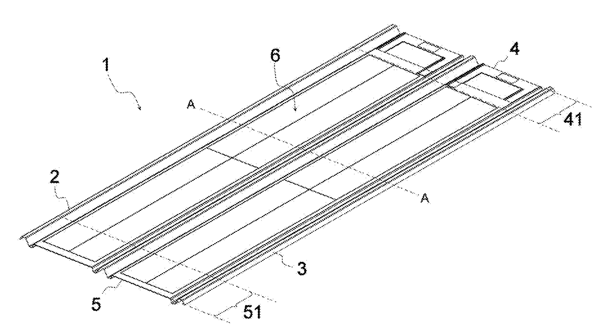
[0067]According to the invention, central part 6 is flat.
second embodiment
[0068]According to the invention, central part 6 is mainly flat and comprises longitudinal stiffeners evenly distributed over the entire central part.
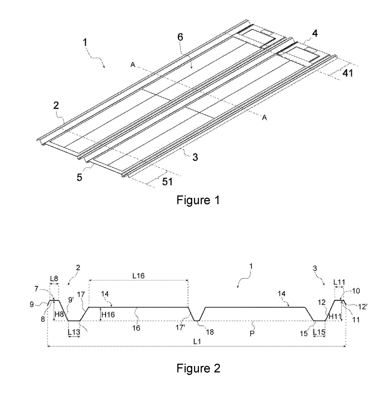
third embodiment
[0069]According to the invention illustrated in FIGS. 2 and 4, central part 6 successively comprises a first base plate 13, at least one projecting part 14 and a second base plate 15. First base plate 13, of width L13, is located in plane P in the extension of lateral base plate 9′ of first longitudinal rib 7. Second base plate 15, of width L15, is located in plane P in the extension of lateral base plate 12 of second longitudinal rib 10. Projecting part 14 comprises an upper plate 16 of height H16 and width L16 and two side web plates 17, 17′ extending from the upper plate on both sides thereof and downward, forming an angle β with plane P. Height H16 here refers to the distance between plane P and the lateral end of the upper plate, i.e., the intersection point of the upper plate and a side web.
[0070]Projecting part 14 serves, in particular, to incorporate a junction box and / or connectors between upper plate 16 and plane P. When the panel is placed on the load-bearing structure of...
PUM
 Abstract
Description
Claims
Application Information
PatSnap Eureka turns technology decisions into work you can execute. Powered by our Innovation Knowledge Graph, it runs expert workflows across engineering, life sciences, materials and intellectual property. Get your review-ready output in minutes.


