Vehicle framework structure

a technology of vehicle framework and structure, applied in the field of vehicle framework structure, can solve problems such as affecting the smooth transmission of load to other parts of the framework, and achieve the effects of reducing weight, improving load transmission efficiency, and excellent advantageous effect of suppressing shear deformation

Active Publication Date: 2018-06-14
TOYOTA JIDOSHA KK
View PDF0 Cites 9 Cited by
  • Summary
  • Abstract
  • Description
  • Claims
  • Application Information

AI Technical Summary

Benefits of technology

[0006]In consideration of the above circumstances, an object of the present invention is to obtain a vehicle framework structure capable of improving load transmission efficiency in a vehicle body structure not provided with a floor tunnel.
[0043]The vehicle framework structure according to the eleventh aspect and the thirteenth aspect exhibits the excellent advantageous effect of enabling an improvement in productivity.

Problems solved by technology

Accordingly, in the configuration described in JP-A No. 2007-106320, there is a possibility that collision load might concentrate between the uniform portion and the intermediate frame in a vehicle collision, hindering the smooth transmission of load to elsewhere in the framework.

Method used


Image

  • Vehicle framework structure
  • Vehicle framework structure
  • Vehicle framework structure

Examples


first exemplary embodiment

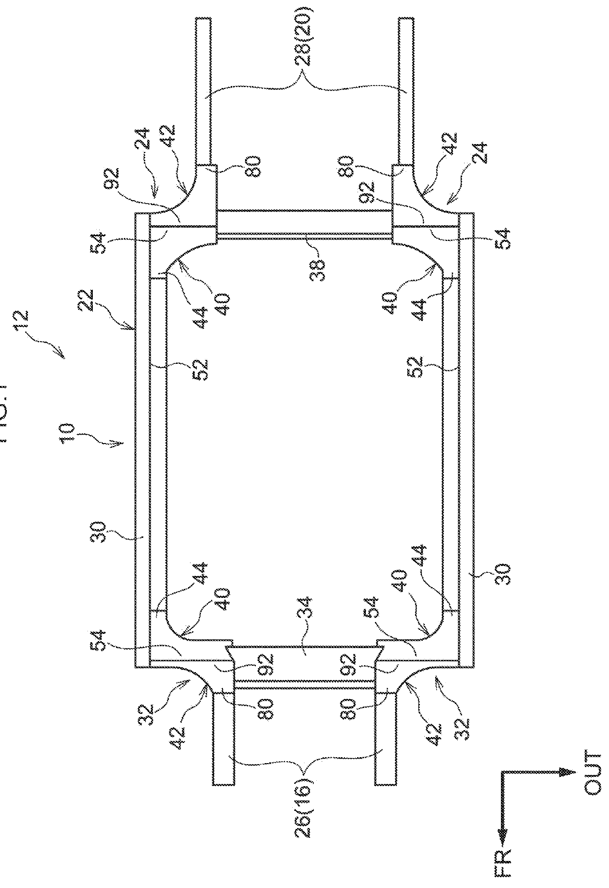
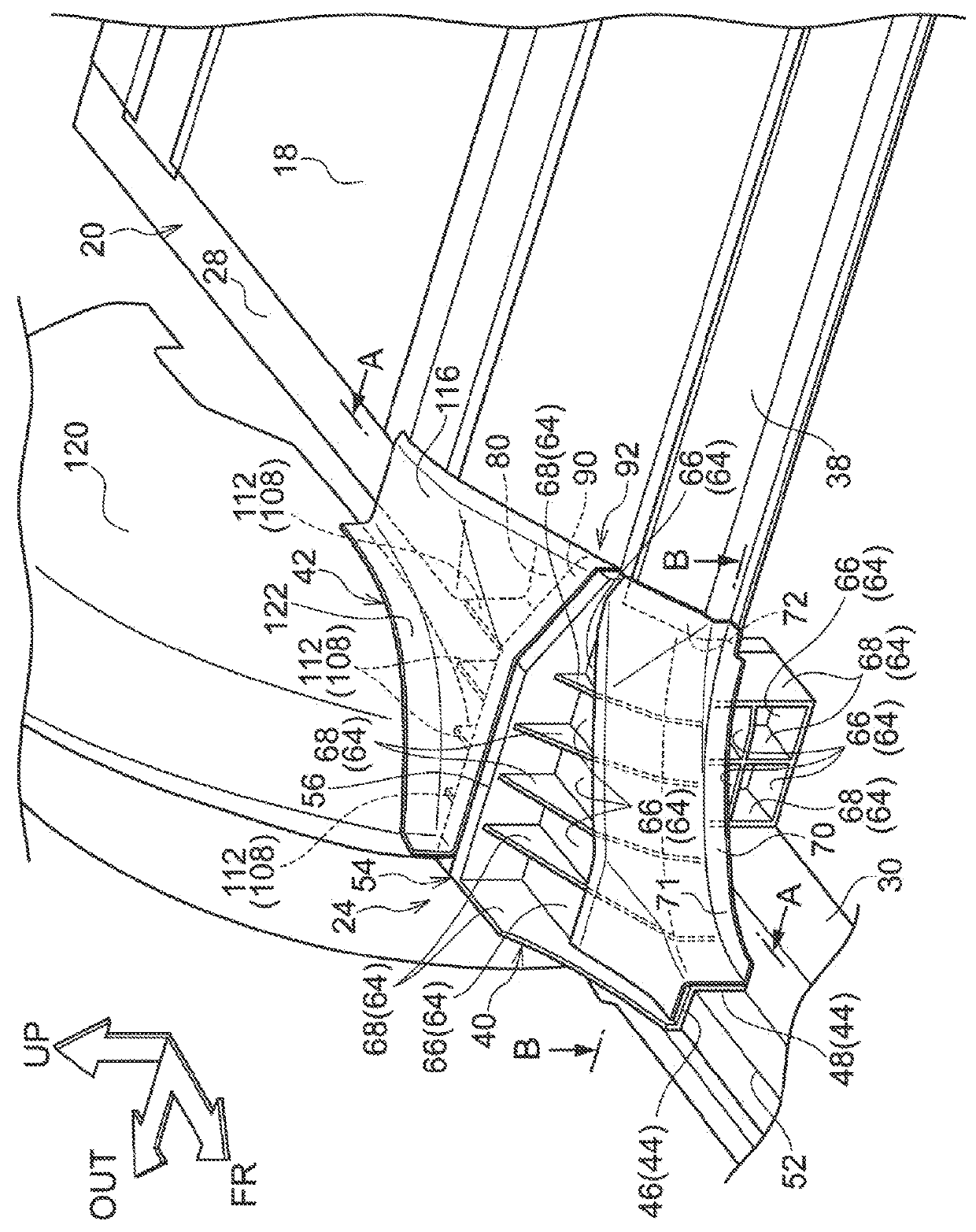
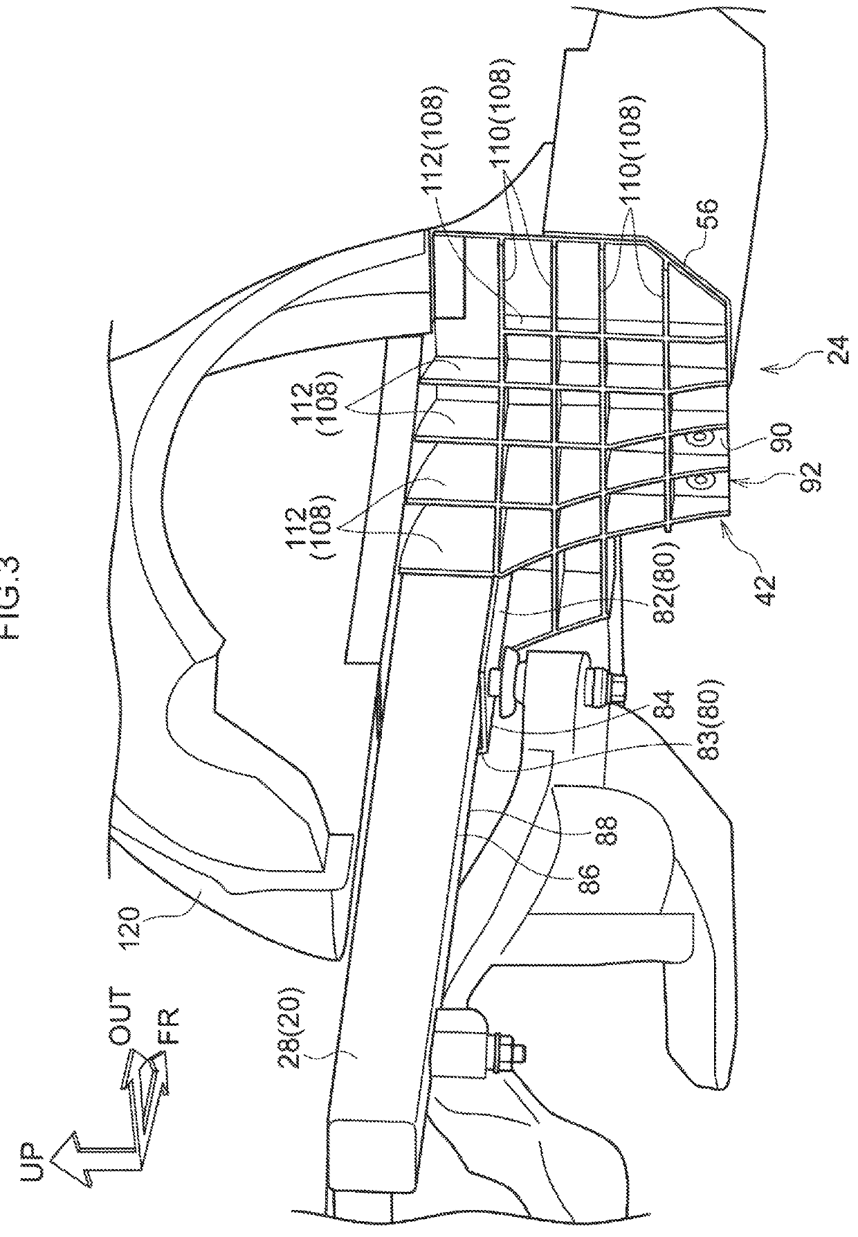
[0055]Explanation follows regarding a first exemplary embodiment of a vehicle framework structure according to the present invention, with reference to FIG. 1 to FIG. 6. Note that in the respective drawings, the arrow FR indicates the front in the vehicle front-rear direction, the arrow OUT indicates the vehicle width direction outer side, and the arrow UP indicates upward in the vehicle vertical direction.

[0056]As illustrated in FIG. 1, a vehicle 12 provided with a vehicle framework structure 10 includes a front frame 16, a rear frame 20, an intermediate frame 22, and coupling sections 24, 32, each located at a vehicle lower side of a floor panel, not illustrated in the drawings. The front frame 16 configures part of the framework of a front section of the vehicle 12, and specifically, is configured including a pair of left and right front-side members 26 extending along the vehicle front-rear direction. A power unit and a front suspension member (neither of which are illustrated i...

modified example

[0083]In the present exemplary embodiment, configuration is made in which the first configuration member 40 and the second configuration member 42 of the coupling section 24 are joined together at the joining wall portions 56, 90. However, there is no limitation thereto, and as illustrated in FIG. 6, for example, configuration may be made in which a projection 142 is formed projecting out from a vehicle width direction outer side of the first configuration member 40 toward the vehicle rear, with the projection 142 being abutted against or joined to a vehicle width direction outer side of the second configuration member 42. Namely, the projection 142 projects out toward the second configuration member 42 of the coupling section 24, and since the projection 142 overlaps with the second configuration member 42 in the vehicle width direction, when load is input to one of the first configuration member 40 or the second configuration member 42 substantially along the vehicle width directi...

second exemplary embodiment

[0085]Next, explanation follows regarding a vehicle framework structure according to a second exemplary embodiment of the present invention, with reference to FIG. 7 to FIG. 10. Note that configuration portions that are basically the same as those of the first exemplary embodiment described above are allocated the same reference numerals, and explanation thereof is omitted.

[0086]The vehicle framework structure according to the second exemplary embodiment has the same basic configuration as the first exemplary embodiment, but is distinctive in the point that a hollow portion 152 is provided inside a coupling section 150.

[0087]Namely, as illustrated in FIG. 7, a pair of left and right coupling sections 150 are each configured including a first configuration member 154 and a second configuration member 156. The first configuration member 154 is disposed on the intermediate frame 22 side (not illustrated in FIG. 7), and is formed with a substantially L-shaped profile in vehicle front vi...


PUM


Abstract

The present disclosure presents a vehicle framework structure, which comprises: a front frame that configures a part of a framework of a vehicle front section; a rear frame that configures a part of a framework of a vehicle rear section; an intermediate frame that configures a part of a framework of a vehicle intermediate section, and that includes a framework member disposed between the front frame and the rear frame and having a length direction in a vehicle front-rear direction; and a coupling section that includes a first configuration member attached to the framework member of the intermediate frame so as to be continuous with the framework member in the vehicle front-rear direction, and a second configuration member attached to the first configuration member so as to be continuous with the first configuration member in the vehicle front-rear direction.

Description

CROSS-REFERENCE TO RELATED APPLICATION[0001]This application is based on and claims priority under 35 USC 119 from Japanese Patent Application No. 2016-239805 filed on Dec. 9, 2016, the disclosure of which is incorporated by reference herein.BACKGROUNDTechnical Field[0002]The present invention relates to a vehicle framework structure. Related Art[0003]Japanese Patent Application Laid-Open (JP-A) No. 2007-106320 describes a vehicle frame structure. The frame structure includes a front frame configuring framework at a vehicle front section, a rear frame configuring framework at a vehicle rear section, and an intermediate frame configuring framework between the front frame and the rear frame. A uniform portion capable of selectively changing length in a vehicle front-rear direction can be attached to one vehicle front-rear direction end portion of the front frame and the rear frame.[0004]The vehicle framework can accordingly be easily lengthened or shortened in the vehicle front-rear d...

Claims


Application Information

Patent Timeline
Patent Type & Authority Applications(United States)
IPC IPC(8): B62D21/15B62D21/02B62D27/02
CPCB62D21/02B62D25/20B62D25/2009B62D21/07B62D21/15
Inventor TAKAHASHI, NAOKI
Owner TOYOTA JIDOSHA KK
Why Eureka
Try Eureka