
High-bearing-capacity pavement structure and paving construction method
A technology of pavement structure and construction method, which is applied in the direction of roads, roads, road construction reinforcements, etc., can solve problems affecting the integrity of pavement structure, detachment of asphalt concrete layer, interface slippage, etc., so as to reduce the risk of interlayer slippage, The effect of strengthening the strength of the base and saving the construction period
- Summary
- Abstract
- Description
- Claims
- Application Information
AI Technical Summary
Problems solved by technology
Method used
Image

Examples
Embodiment 1
like Figure 1-6 , a high bearing capacity pavement structure, comprising a graded gravel layer 4, a mortar layer 9 is laid above the graded gravel layer 4, an adhesive layer 10 is laid above the mortar layer 9, and the adhesive layer 10 is laid above There is an asphalt concrete overlay 12;
The bonding layer 10 is provided with a reinforcing bar cage 11 , the upper and lower sides of the reinforcing bar cage 11 are provided with a plurality of outwardly extending outer bars 114 at equal intervals, and the outer bars 114 on the upper and lower sides respectively extend to the lower layer of the bonding layer 10 . The mortar layer 9 and the asphalt concrete overlay layer 12 on the upper layer of the adhesive layer 10.
[0024] In a preferred solution, the cement mortar 6 is spread in the graded gravel layer 4 to form a gravel grouting layer.
[0025] In a preferred solution, the adhesive layer 10 is selected from modified emulsified asphalt.
[0026] In this example, the mod...
Embodiment 2
like Figure 7 , on the basis of Embodiment 1, the reinforcing bar cage 11 includes a plurality of main bars 111, and the plurality of main bars 111 are connected and bound by stirrups 112 to form a main structure of the reinforcing bar cage 11 with a rectangular cross-section. An auxiliary rib 113 is disposed between two adjacent main ribs 111 on the plane, and the outer rib 114 is obliquely welded and fixed on the auxiliary rib 113 .
[0029] The reinforcement cage 11 can be further added with spiral reinforcement to increase the strength of the reinforcement cage 11 and achieve the purpose of increasing the bearing capacity of the pavement.
Embodiment 3
Based on the above embodiments, the paving construction method of the high bearing capacity pavement structure comprises the following steps:
1) Leveling the site and erecting formwork;
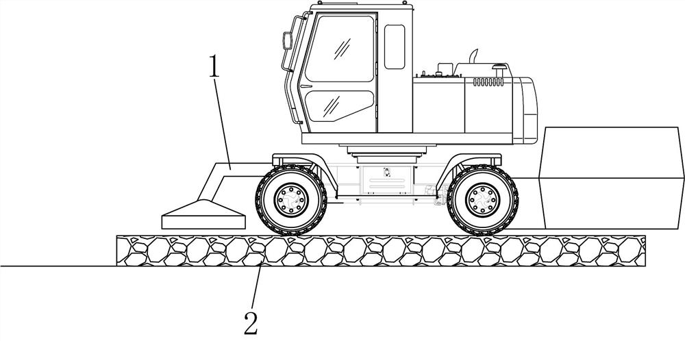
2) Use the gravel paver 1 to spread the large-sized gravel layer 2;
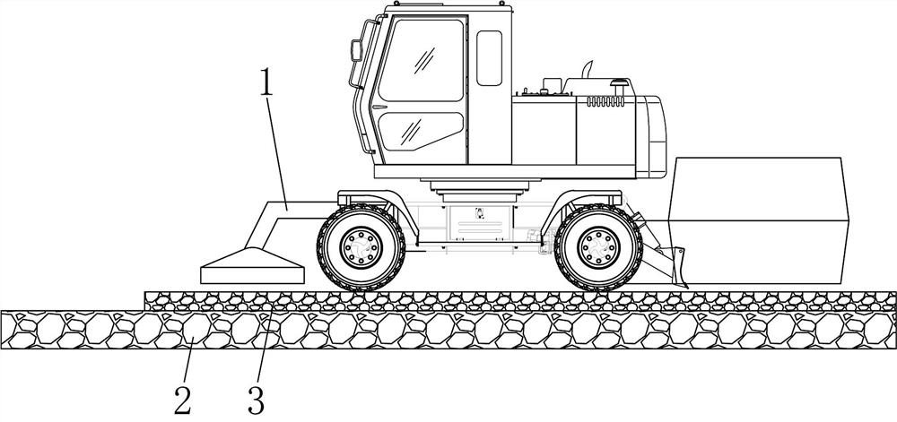
3) Use the gravel paver 1 to spread the small-sized gravel layer 3 on the large-sized gravel layer 2;
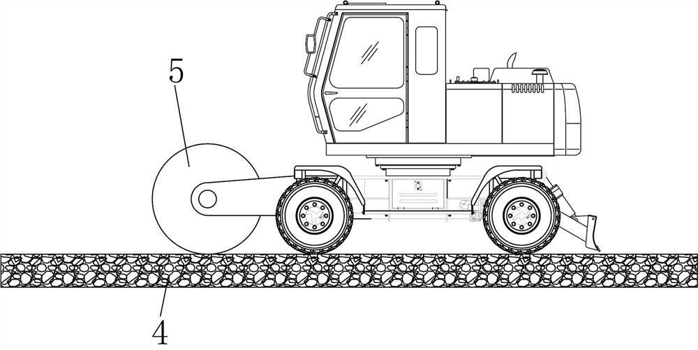
4) Rolling the small-diameter gravel layer 3 with the road roller 5 and mixing the small-diameter gravel layer 3 into the gap of the large-diameter gravel layer 2 to form a graded gravel layer 4;
5) Use the cement paver 7 to spread the cement mortar 6 above the graded gravel layer 4, so that the cement mortar 6 penetrates into the gap of the graded gravel layer 4 to form a gravel grouting layer;
6) Install the reinforcement cage 11 above the graded gravel layer 4, and use the outer reinforcement 114 below the reinforcement cage 11 to form support;
7) Lay the mortar layer 9 above the graded gravel layer 4;
8) Lay the ...
PUM
 Abstract
Description
Claims
Application Information