Onboard diagnostics of an active air dam assembly

a technology of air dam and diagnostics, applied in the direction of electronic commutators, propulsion parts, transportation and packaging, etc., can solve the problems of flap failure, controller cannot ordinarily determine, flap itself has failed, etc., and achieve the effect of accurate identification of the root caus

Active Publication Date: 2018-06-14
GM GLOBAL TECH OPERATIONS LLC
View PDF2 Cites 9 Cited by
  • Summary
  • Abstract
  • Description
  • Claims
  • Application Information

AI Technical Summary

Benefits of technology

[0002]A system and method are disclosed herein for automatically diagnosing a fault mode in an active air dam assembly of the type generally described above. The air dam assembly may include an adjustable flap that is actuated by a flap motor or other actuator. As part of closed-loop control of the flap actuator, a position, a current draw, and a back-electromotive force (back-EMF) of the flap actuator may be individually sensed or calculated by a controller. For instance, a position sensor may be used to measure an output position of the flap actuator, e.g., of a rotor shaft thereof, from which a relative position of the flap may be determined, or the flap position may be directly measured. However, if the flap position differs from a controller-commanded flap position, the controller cannot ordinarily determine, absent use of the present method, whether the position sensor or the flap has failed. The present disclosure is therefore intended to help address this potential performance issue without requiring the use of addition sensor hardware, while at the same time enabling accurate identification of a root cause of a detected fault mode.

Problems solved by technology

However, if the flap position differs from a controller-commanded flap position, the controller cannot ordinarily determine, absent use of the present method, whether the position sensor or the flap has failed.
When the flap position sensor data and the current draw correlate sufficiently well, but reflect a flap position that is different from the commanded flap position, the controller may instead determine that the flap itself has failed and instead register a flap fault.

Method used


Image

  • Onboard diagnostics of an active air dam assembly
  • Onboard diagnostics of an active air dam assembly
  • Onboard diagnostics of an active air dam assembly

Examples


Embodiment Construction

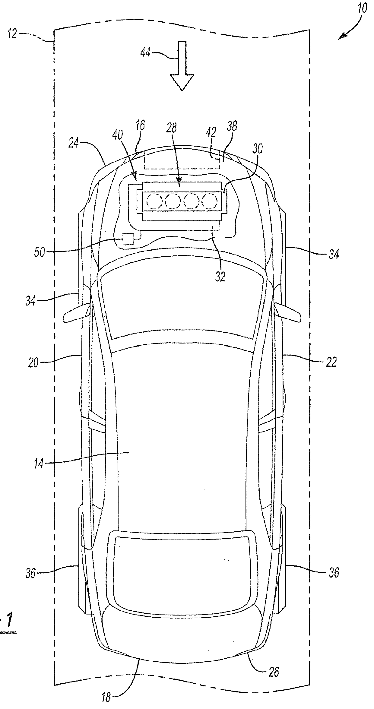
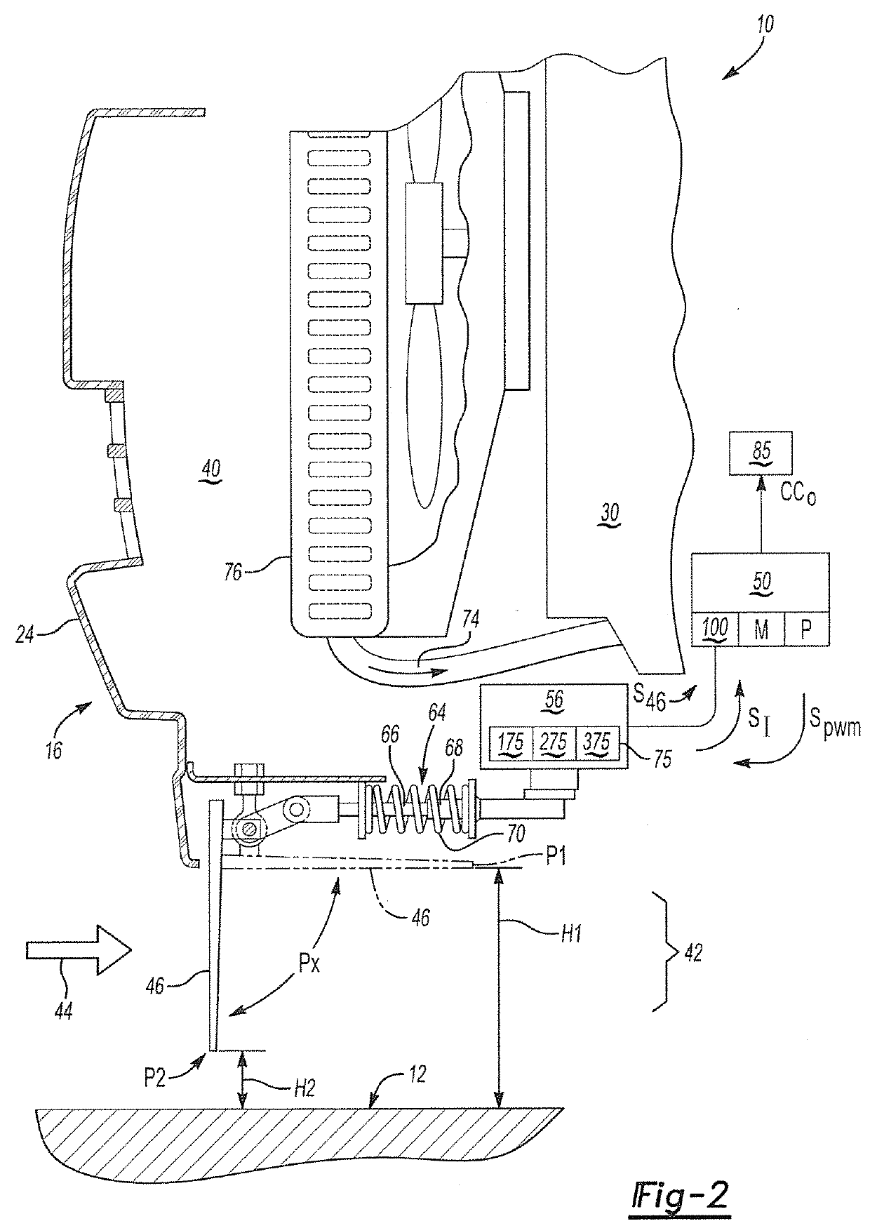
[0019]Referring to the drawings, wherein like reference numbers refer to like components, FIG. 1 shows an example vehicle 10 positioned relative to a road surface 12. The vehicle 10 includes an active air dam assembly 42 and a controller 50, with the controller 50 configured to regulate ongoing operation of the active air dam assembly 42. As explained below in detail with reference to FIGS. 2-5, the controller 50 is also configured to perform onboard diagnostics of the active air dam assembly 42 and thereby identify specific fault modes of the air dam assembly 42 from among a plurality of different possible fault modes as explained in detail herein.

[0020]The vehicle 10 of FIG. 1 includes a vehicle body 14. The body 14 in turn defines two body ends, i.e., a first or front end 16 and a second or rear end 18. The body also defines two lateral sides, i.e., a left side 20 and a right side 22, with the terms “front”, “rear”, “left”, and “right” referring to the perspective of an operator ...


PUM


Abstract

A vehicle includes a body and an active air dam assembly. The body has a first end facing an ambient airflow and a second end facing away from the ambient airflow. The assembly is disposed at the first or second end and controls the ambient airflow between the body and a road surface. The assembly includes an adjustable flap, an actuator, sensors, and a controller. The flap shifts between different stowed and deployed positions. The actuator moves the flap, e.g., via a shaft. Each sensor measures a separate performance parameter of the actuator. The controller executes a method to receive the measured performance parameters, identify a fault mode of the air dam assembly from among different possible fault modes using the performance parameters, and execute a control action corresponding to the identified fault mode.

Description

INTRODUCTION[0001]The disclosure relates to a system and method for performing onboard diagnostics for an active air dam assembly. Motor vehicles utilize ambient airflow to cool powertrain components situated in an underhood compartment. Ambient airflow may enter the underhood compartment from beneath the vehicle body or through a front grille opening. An actuator-controlled air dam assembly, also variously referred to as an active gurney, a front splitter, or a front spoiler, may be positioned below or integrated with a front bumper of the vehicle. A deployable air dam door or flap is selectively deployed or stowed with respect to the ambient airflow so as to control the amount of ambient airflow entering the underhood compartment. Additionally, the position of the flap can be adjusted to generate a desired aerodynamic downforce on the vehicle body in order to enhance overall vehicle dynamics and handling.SUMMARY[0002]A system and method are disclosed herein for automatically diagn...

Claims


Application Information

Patent Timeline
Patent Type & Authority Applications(United States)
IPC IPC(8): B62D35/02H02P6/16
CPCH02P6/16B62D35/02B60K11/085B60W50/0205H02P6/182B62D35/005B62D37/02Y02T10/82
Inventor ABDOUL AZIZOU, ABDOUL KARIMSUNTHARALINGAM, PIRANAVAN
Owner GM GLOBAL TECH OPERATIONS LLC
Why Eureka
Try Eureka