Smart latch

a technology of smart latches and latches, applied in the direction of passenger lock actuation, electrical locking circuits, lock applications, etc., can solve the problem of delayed “resetting” of the power release mechanism, and achieve the effect of reducing motor nois

Active Publication Date: 2018-06-14
MAGNA CLOSURES INC
View PDF0 Cites 31 Cited by
  • Summary
  • Abstract
  • Description
  • Claims
  • Application Information

AI Technical Summary

Benefits of technology

[0015]As a result of these and other aspects, the latch assembly of the present disclosure functions to mechanically hold the pawl in its ratchet releasing position via the over-center relationship established between reaction forces exerted by the backdrive lever on the cam segment of the power release gear and a rotary axis of the power release gear. Accordingly, this arrangement assures that the latch assembly remains in a released state in the event of a power failure.
[0016]Additionally, the reset operation only requires limited actuation of the electric motor to drive the power release gear in the resetting direction from its actuated position to its release position for shifting the reset mechanism from its first over-center state into its second over-center state at which point the spring-loaded backdrive lever takes over to forcibly drive the power release gear back to its rest position. This limited use of the electric motor during the reset operation assures resetting of the power-operated latch release mechanism in the event of a power failure as well as reducing motor noise.
[0017]Further, the mechanical backup reset mechanism allows the vehicle operator to backdrive the motor by manually rotating the power release gear from its actuated position to its release position for manually shifting the reset mechanism from its first over-center state into its second over-center state at which point the spring-loaded backdrive lever takes over to forcibly drive the power release gear back to its rest position. This manual actuation of the backup reset mechanism provides tactile feedback as a result of the limited backdriving of the electric motor that is required.
[0018]The latch assembly of the present disclosure employs a direct connection between the pawl of the latch mechanism and the power release gear of the power-operated latch release mechanism to provide coordinated movement therebetween. This direct connection is configured in a stacked or overlaid arrangement within the arc travel of the power release gear so as to provide a compact packaging.

Problems solved by technology

Such swinging passenger doors (“swing doors”) have recognized issues such as, for example, when the vehicle is situated on an inclined surface and the swing door either opens too far or swings shut due to the unbalanced weight of the door.
Further, the “resetting” of the power release mechanism must be delayed until sufficient movement of the door has occurred to prevent unintended latching of the ratchet to the striker.
Additionally, the reset operation only requires limited actuation of the electric motor to drive the power release gear in the resetting direction from its actuated position to its release position for shifting the reset mechanism from its first over-center state into its second over-center state at which point the spring-loaded backdrive lever takes over to forcibly drive the power release gear back to its rest position.

Method used


Image

  • Smart latch
  • Smart latch
  • Smart latch

Examples


Embodiment Construction

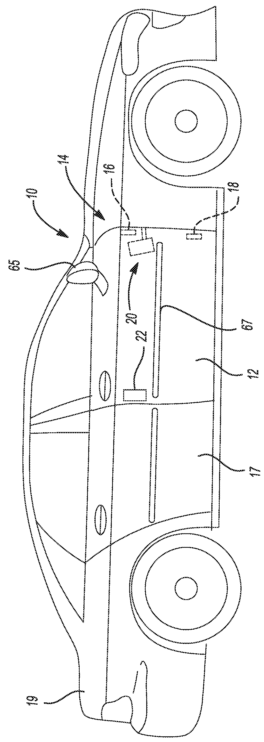
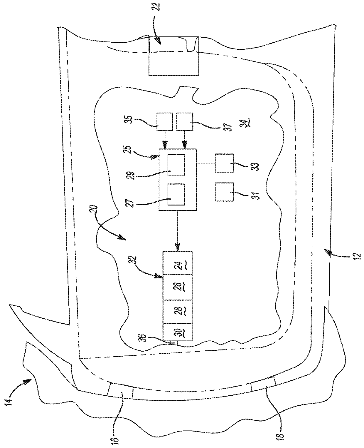
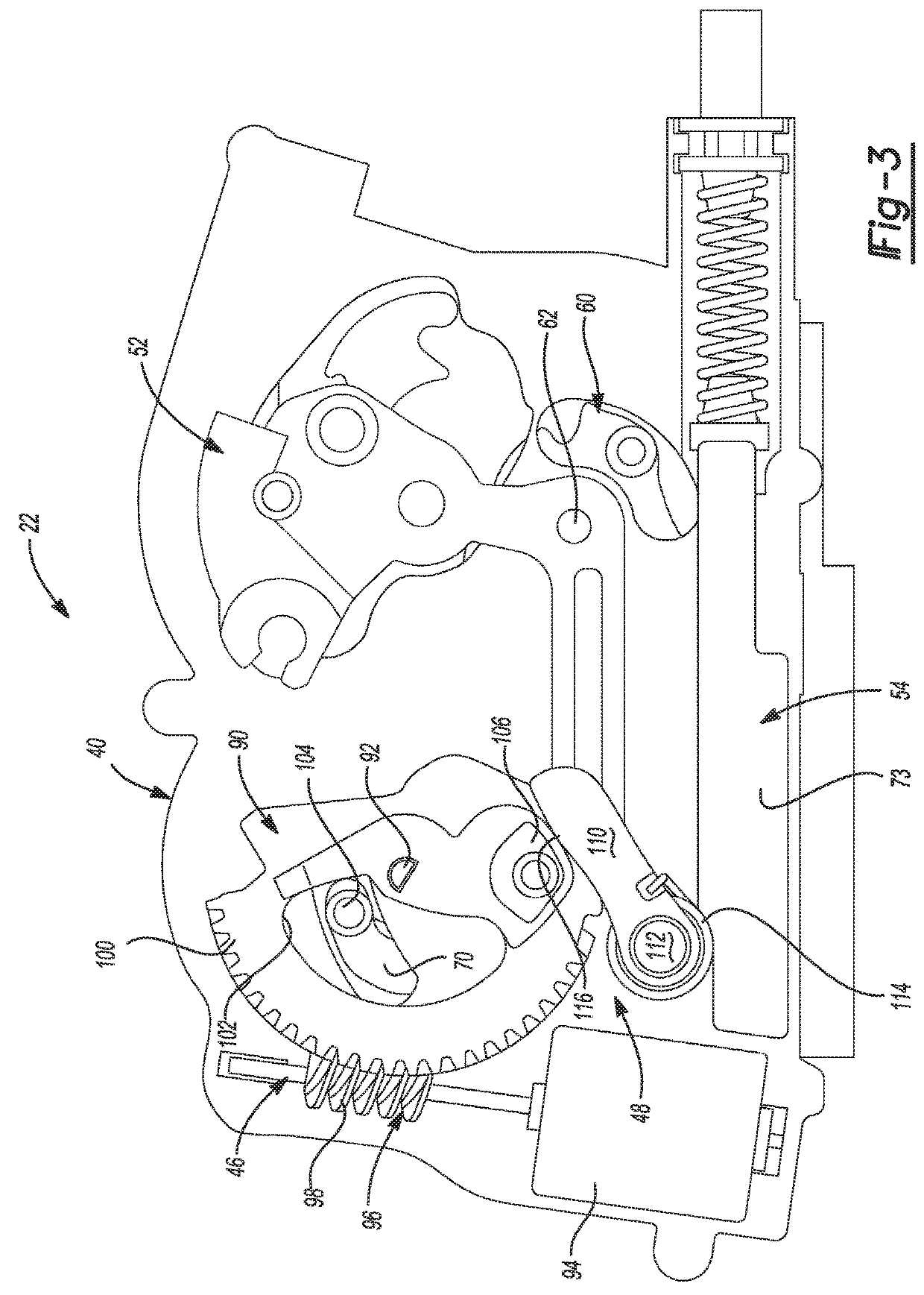
[0034]Example embodiments of a latch assembly for use in motor vehicle closure systems, constructed in accordance with the teachings of the present disclosure, will now be disclosed. The example embodiments of the latch assembly are further illustrated and described in association with a power swing door actuation system. These example embodiments are provided so that this disclosure will be thorough, and will fully convey the scope to those who are skilled in the art. Numerous specific details are set forth such as examples of specific components, devices, and methods, to provide a thorough understanding of embodiments of the present disclosure. It will be apparent to those skilled in the art that specific details need not be employed, that example embodiments may be embodied in many different forms and that neither should be construed to limit the scope of the disclosure. In some example embodiments, well-known processes, well-known device structures, and well-known technologies a...


PUM


Abstract

A latch assembly for a motor vehicle includes a latch mechanism, a power-operated latch release mechanism, and an over-center spring-biased reset mechanism. The power-operated latch release mechanism is operable during a power release operation to shift the reset mechanism from a first over-center operating state into a second over-center operating state.

Description

CROSS-REFERENCE TO RELATED APPLICATIONS[0001]This application claims the benefit of U.S. Provisional Application No. 62 / 433,974, filed on Dec. 14, 2016. The entire disclosure of the above application is incorporated herein by reference.BACKGROUND[0002]The present disclosure relates generally to power closure systems for motor vehicles. More specifically, the present disclosure is directed to a latch assembly configured for installation in a power swing door closure system and having a power-operated latch release mechanism and an over-center reset mechanism.RELATED ART[0003]This section provides background information related to the present disclosure which is not necessarily prior art.[0004]The passenger doors on motor vehicles are typically mounted by a pair of door hinges to the vehicle body for swinging movement about a generally vertical pivot axis. Such swinging passenger doors (“swing doors”) have recognized issues such as, for example, when the vehicle is situated on an incl...

Claims


Application Information

Patent Timeline
Patent Type & Authority Applications(United States)
IPC IPC(8): E05B81/14E05B81/16E05B81/06E05B81/36E05B85/26E05B81/50
CPCE05B81/14E05B81/16E05B81/06E05B81/36E05B85/26E05B81/50E05B77/22E05B77/36E05B81/32E05B81/34E05B81/90E05B83/36E05B81/20E05B81/42
Inventor PATANE, FRANCESCOQUARTIERI, CARLOBOERI, ENRICO
Owner MAGNA CLOSURES INC
Why Eureka
Try Eureka