Framework for universally specified affinity topologies with partial path invalidation and generalized network flows

a network flow and affinity topology technology, applied in the field of network switch systems, can solve the problems of excessive delay in data communication between servers that are not co-located within the same rack, excessive latency skew of broadcast and/or multicast data, and exacerbate latency and/or latency skew

Active Publication Date: 2018-06-14
HEWLETT-PACKARD ENTERPRISE DEV LP
View PDF0 Cites 41 Cited by
  • Summary
  • Abstract
  • Description
  • Claims
  • Application Information

AI Technical Summary

Problems solved by technology

For example, data communications between servers that are not co-located within the same rack may experience excessive delay (also referred to herein as “latency”) within the data center network, due in no small part to the multitude of switches and / or routers that the data may be required to traverse as it propagates up, down, and / or across the hierarchical architecture of the network.
Further, because multiple paths may be employed to deliver broadcast and / or multicast data to different destinations within the data center network, such broadcast and / or multicast data may experience excessive latency skew.
Such latency and / or latency skew may be exacerbated as the size of the data center network and / or its load increases.
The hierarchical architecture of the data center network also generally suffers from increasingly complex fiber cabling requirements as the numbers of switches, routers, layers, and their interconnections are increased to handle the expansion of the data center network.
As these data center networks grow in size, the routing between nodes also becomes more complicated.
However, as the size of the tree grows, the number of potential failures on the tree also grows.
This can lead to problems where a problem in one link may invalidate the entire tree for every node it touches.

Method used


Image

  • Framework for universally specified affinity topologies with partial path invalidation and generalized network flows
  • Framework for universally specified affinity topologies with partial path invalidation and generalized network flows
  • Framework for universally specified affinity topologies with partial path invalidation and generalized network flows

Examples


Embodiment Construction

[0039]This patent application claims priority from U.S. Provisional Patent Application No. 62 / 431,678, filed Dec. 8, 2016, and U.S. Provisional Patent Application No. 62 / 583,072, filed Nov. 8, 2017, the disclosures of which are incorporated by reference herein in their entirety.

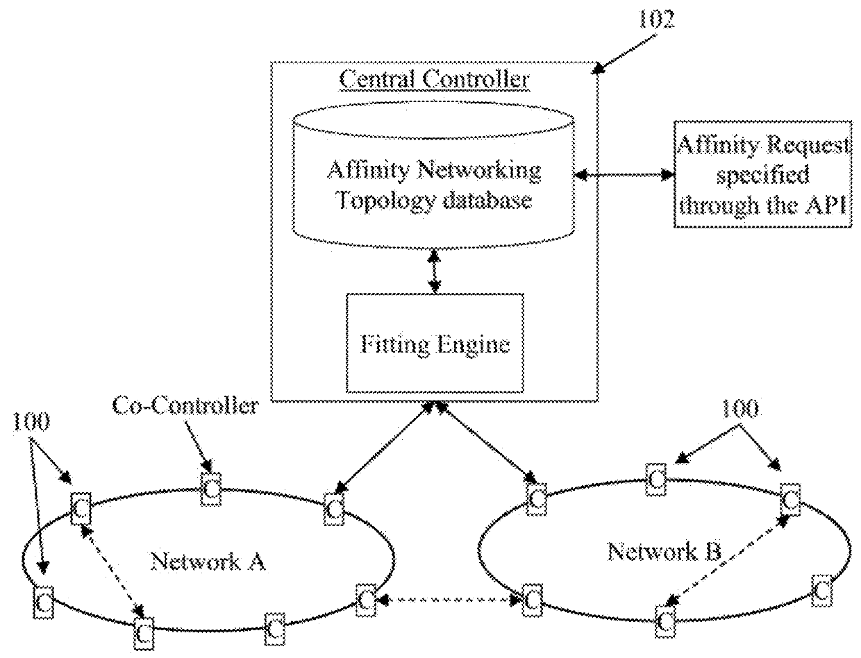
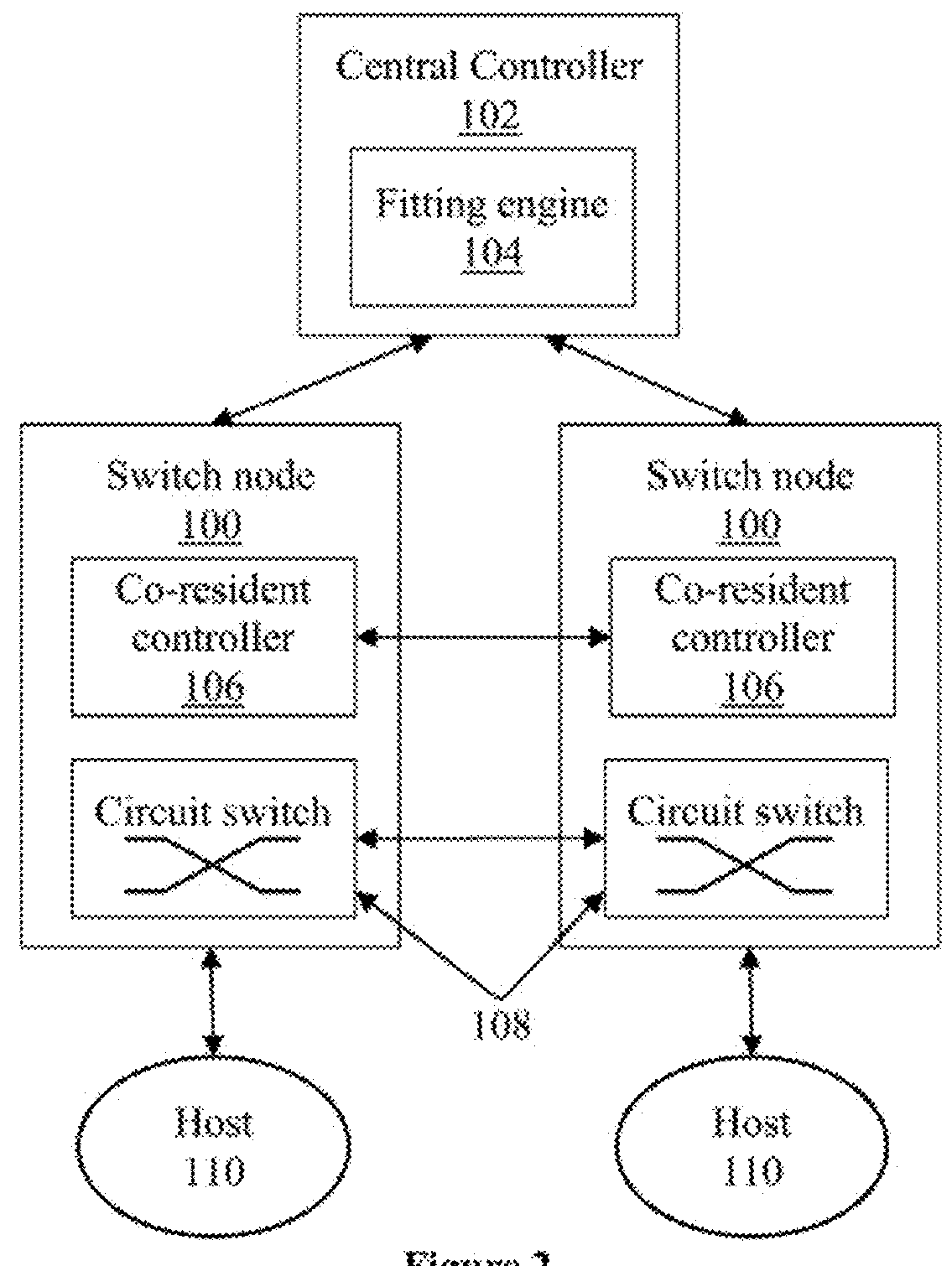
[0040]Data center networks can employ optical network topologies and optical nodes to efficiently allocate bandwidth within the data center networks, while reducing the physical interconnectivity requirements of the data center networks. Such data center networks provide a hierarchy of control for controlling and provisioning computing resources within the data center networks, based at least in part on the network topology and an application component topology. Such control and provisioning of computing resources includes determining a combined affinity-network topology for a data center network (e.g., a network topology which is designed based on requirements between applications running on various elements...


PUM


Abstract

A method for setting up forwarding tables is described. A USAT part for a node is received. The USAT part includes glow definitions and a FGPL. Each glow describes network traffic flows and role instructions for the flows. Each FGP describes a role for the switching node; a validity rule; and relevant network topology. The method also includes determining a selected active FGP in the FGPL using the validity rule for the FGP, a network state and the ordering of the FGPs; initializing the glows, requesting a role identification to perform based on the selected FGP, determining the role instructions and instructing the TMS to update tables accordingly; and storing entries in software tables based on glows and the role instructions for the identified role, dynamically resolving conflicts among entries, and granting table updates to hardware tables. The tables include a software table for each hardware memory for forwarding packets.

Description

BACKGROUND OF THE INVENTION[0001]Various embodiments relate generally to network switch systems, methods, devices and computer programs and, more specifically, relate to network switch systems using partially validated trees which are specified for groups of flows.[0002]This section is intended to provide a background or context. The description may include concepts that may be pursued, but have not necessarily been previously conceived or pursued. Unless indicated otherwise, what is described in this section is not deemed prior art to the description and claims and is not admitted to be prior art by inclusion in this section.[0003]University, government, business, and financial service entities, among others, have increasingly relied upon data center networks. As such, data center networks are generally expanding in terms of the number of servers incorporated therein, as well as the networking equipment needed to interconnect the servers for accommodating the data transfer requirem...

Claims


Application Information

Patent Timeline
Patent Type & Authority Applications(United States)
IPC IPC(8): H04L12/751H04L12/705H04L12/721H04L45/02H04L45/16H04L45/18H04L45/42H04L45/50H04L45/74
CPCH04L45/02H04L45/18H04L45/38H04L45/66H04L45/16H04L45/745H04L12/4641H04L43/0817H04L45/42H04L45/48H04L45/50H04L45/54H04L47/125H04L49/101H04L49/254H04L12/44H04L12/4633H04L41/122H04L45/7452H04L45/488
Inventor BARRY, RICHARD A.ZHANG, LEI
Owner HEWLETT-PACKARD ENTERPRISE DEV LP
Why Eureka
Try Eureka