
Present invention relates to a micro stream emitter for use in irrigation systems and, in particular, a micro stream emitter configured for discharging water at the root ball and soil around plant.

Active Publication Date: 2018-06-21
BRYANT RANDY
View PDF8 Cites 1 Cited by
  • Summary
  • Abstract
  • Description
  • Claims
  • Application Information

AI Technical Summary

Benefits of technology

The present invention introduces micro stream emitters which combine the benefits of surface spray and drip irrigation. These micro emitters operate with low pressures and can compensate for pressure differences, allowing for accurate application. This technology provides reliable and efficient irrigation for plants, trees, and shrubs, with no excess runoff or waste.

Problems solved by technology

A reoccurring problem with present-day drip irrigation system has been prolonged exposure to overwatered conditions that can cause some of the roots to die back due to a lack of oxygen.
In addition, the drip emitter may restrict root development.
This led to very restricted root growth around the few points of moisture and thus to stunted plant growth.
Drip emitters do not cleanse the foliage.
An additional problem with drip emitter is it does not create humidity.
Finally, you cannot see the drip system working.
For others, not being able to watch the watering is slightly unsettling.
In a poorly designed system, a clogged emitter goes unnoticed until drought stress affects the plant visibly.
The problem with mist emitters is that different plants require different precipitation rates.
Moreover, because the pinhole is quite tiny, it tends to clog up.

Method used


Image

  • Present invention relates to a micro stream emitter for use in irrigation systems and, in particular, a micro stream emitter configured for discharging water at the root ball and soil around plant.
  • Present invention relates to a micro stream emitter for use in irrigation systems and, in particular, a micro stream emitter configured for discharging water at the root ball and soil around plant.
  • Present invention relates to a micro stream emitter for use in irrigation systems and, in particular, a micro stream emitter configured for discharging water at the root ball and soil around plant.

Examples


Embodiment Construction

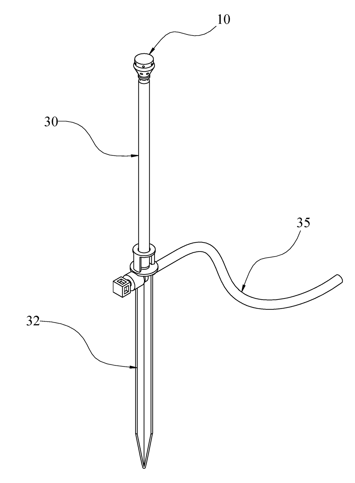
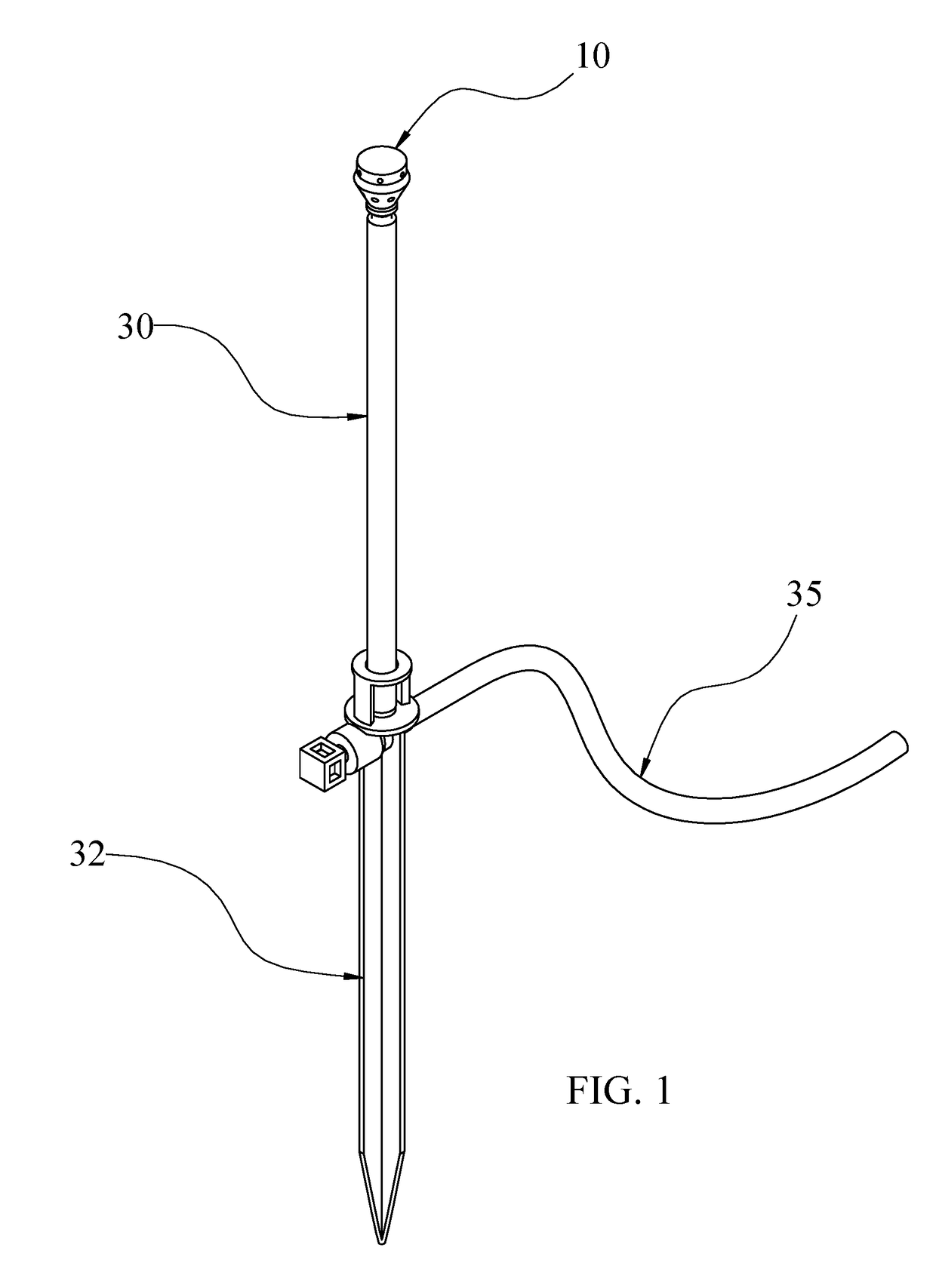
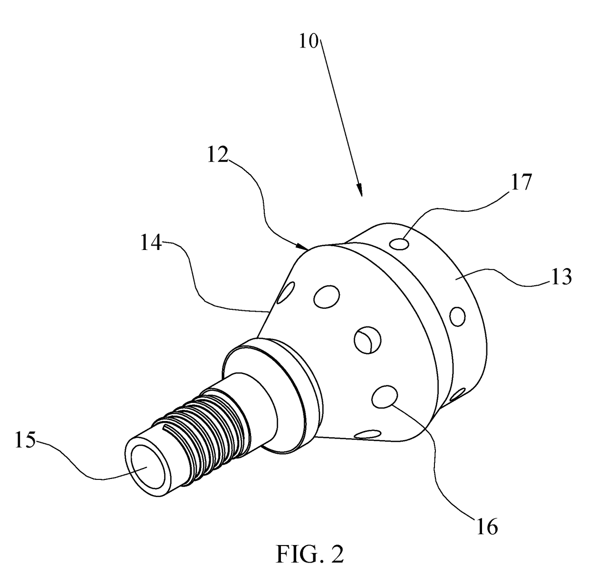
[0031]In the following detailed description of the preferred embodiment, reference is made to the accompanying drawings, which form a part of this application. The drawing show, by way of illustration, specific embodiments in which the invention may be practiced. It is to be understood that other embodiments may be utilized and structural changes may be made without departing from the scope of the present invention. As generally shown in FIG. 1 the present invention is directed to a micro stream emitter 10, which when these micro stream emitters connected to a drip riser 30, attached to an adjustable flow stake 32. When connected to an water supply tube 35 which delivers water under pressure to the micro stream emitters 10 for purposes of watering or irrigating the area surrounding the micro stream emitters. As substantially shown in FIG. 2, the micro stream emitter 10, has a sturdy plastic body 12 formed of an upper portion 13, and a lower portion 14, within a circular profile. The...


PUM


Abstract

a highly efficient and serviceable micro stream emitter that is a truly remarkable innovation with a low precipitation rate, highly uniform distribution, and increased radius range, all in a emitter which providing a flat stream and simultaneously down stream spray. The micro stream emitter include a body having two different geometries water outlet ports providing downward stream into the soil wetting the root zone and with the second geometries water outlet wetting the surrounding plants area. The internal passage of the emitter shown a the lower passage suppling water to the lower ports that actually uses top wall with a annular depression, forming a diaphragm enabling the water to reflex into the lower port outlets. Similar to the internal lower passage the upper passage with includes a smaller diameter passage uses top wall with an annular depression, forming a diaphragm enabling the water to reflex into the upper port outlets

Description

FIELD OF THE INVENTION[0001]The present invention relates to a micro stream emitter for use in irrigation systems and, in particular, a micro stream emitter configured for discharging water at the root ball and soil around plant.BACKGROUND OF THE INVENTION[0002]Over the years, there have been a number of technological developments in the field of irrigation. Irrigation is the method in which controlled amount of water is supplied to plants at regular intervals for agriculture. Although all irrigation systems provide water to plants, the methods for doing so vary widely.[0003]Localized irrigation is a system where water is distributed under low pressure through a piped network, in a pre-determined pattern, and applied as a small discharge to each plant or adjacent to it. Drip irrigation, spray or micro-sprinkler irrigation and bubbler irrigation belong to this category of irrigation methods.[0004]In addition, localized irrigation considered a type of low-pressure irrigation typically...

Claims


Application Information

Patent Timeline
IPC IPC(8): B05B1/14A01G25/02B05B15/06
CPCB05B1/14B05B15/622A01G25/023
Inventor BRYANT, RANDY SCOTT
Owner BRYANT RANDY
Learn More