Method and Device for Producing a System Having a Component Applied to a Predetermined Location of a Surface of a Substrate

Inactive Publication Date: 2006-11-16
BOCK KARLHEINZ
View PDF14 Cites 0 Cited by
  • Summary
  • Abstract
  • Description
  • Claims
  • Application Information

AI Technical Summary

Benefits of technology

[0013] Further, the present invention is based on the idea to use special surface structures on the component or the microchip or the substrate, respectively, to cause a lateral self adjustment and preferably simultaneously an alignment of the component relative to the substrate preferably in cooperation with the liquid medium.
[0014] More generally, according to the present invention the component or the predetermined location of the surface of the substrate to which the component is to be applied are implemented so that after the application of the liquid volume a force acts on the component which is sufficient to drive or move, respectively, the component within the liquid volume to the predetermined location by itself or for example together with a Brownian movement of the same.
[0015] As, according to the present invention, a preferably very small liquid volume is preferably applied very accurately to the location to which the component is to be applied on the surface of the substrate or where it later has to fulfill its function, respectively, the component will reach the predetermined location from the outside very fast and without further ado. In other words, according to the present invention, in contrast to a pure self assembly method in which the whole substrate is immersed into a liquid containing the component, a large part of the probability process of the approximation of the component to the predetermined location is prevented or shortened, respectively. Such a probability process would for example be an arbitrary movement of the component which would have to be supporte

Problems solved by technology

The described processes or method steps and thus the loading of a substrate with components using a pick-and-place-method is therefore generally very time-intensive.
Therefore, only a limited throughput may be achieved in production.
In particular, for

Method used


Image

  • Method and Device for Producing a System Having a Component Applied to a Predetermined Location of a Surface of a Substrate
  • Method and Device for Producing a System Having a Component Applied to a Predetermined Location of a Surface of a Substrate
  • Method and Device for Producing a System Having a Component Applied to a Predetermined Location of a Surface of a Substrate

Examples


Embodiment Construction

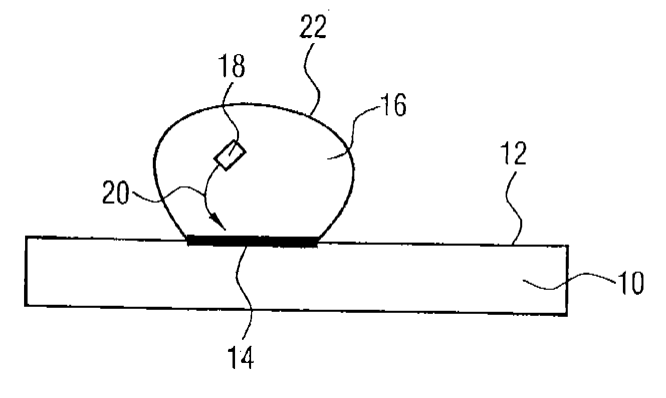
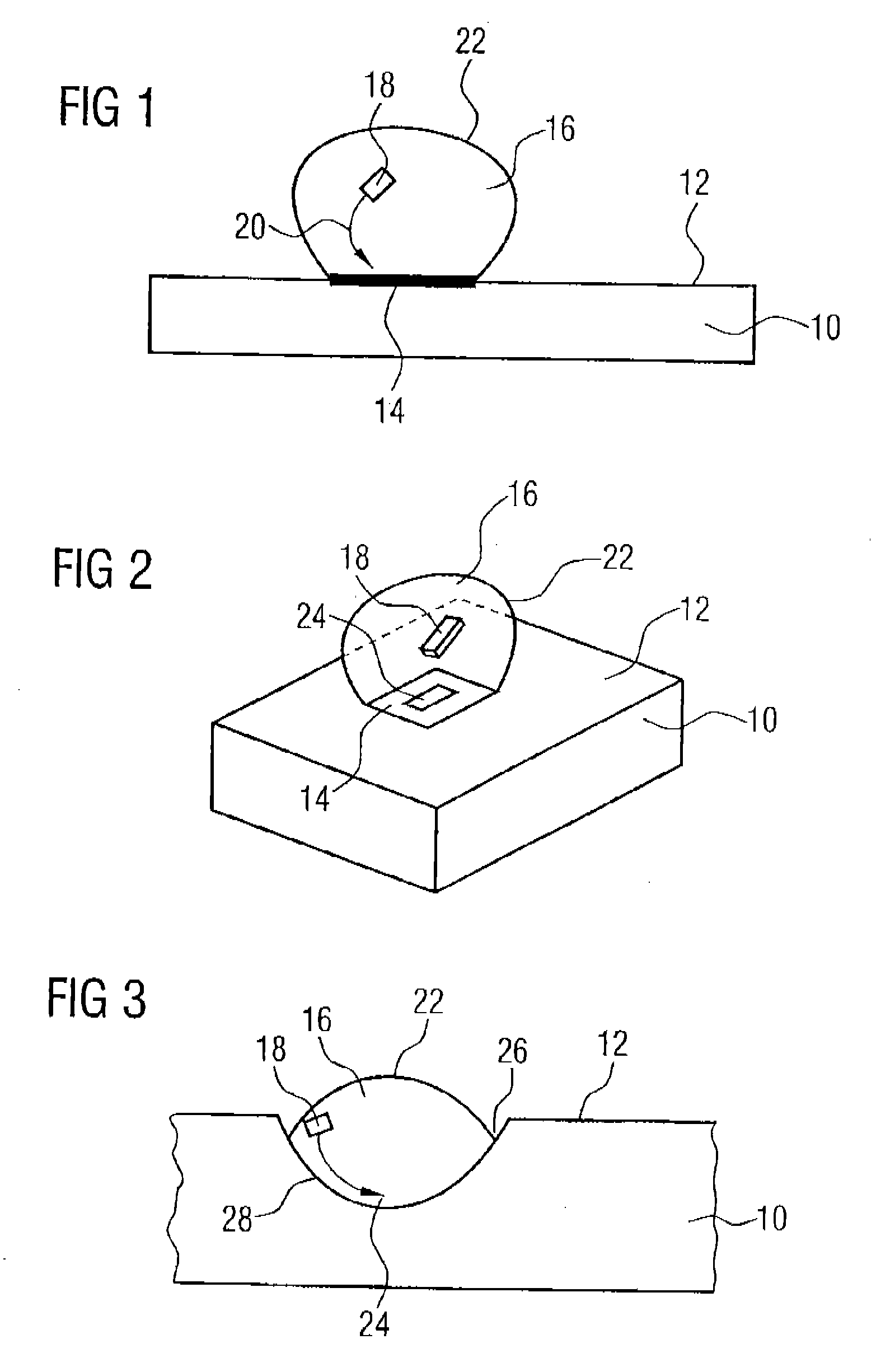
[0023]FIG. 1 is a schematical illustration of a substrate 10 with a surface 12 according to a first embodiment of the present invention. A partial area 14 of the surface 12 is wetted by a liquid volume 16 containing a component 18. The substrate 10 is for example a printed circuit board, a ceramic substrate, paper or foil, a semiconductor substrate or another substrate, to which or to whose surface 12, respectively, the component 18 is to be applied. The component 18 is for example an electronic, microelectronic or micromechanical device which in turn for example consists of a semiconductor material or of plastics. The component 18 was for example formed together with many other like components in a device substrate and was then separated. The component 18 preferably comprises dimensions in a range from 1 nm to one or few mm.

[0024] The liquid volume 16 containing the component here is a drop which was for example applied to the surface 12 of the substrate 10 by an inkjet printing a...


PUM

PropertyMeasurementUnit
Volumeaaaaaaaaaa
Speedaaaaaaaaaa
Areaaaaaaaaaaa

Abstract

A method for producing a system with a substrate with a surface and a component applied to a predetermined location of the surface of the substrate includes a step of generating a liquid volume containing the component and a step of applying the liquid volume containing the component on the surface of the substrate. At that, the liquid volume is sized so that it wets only a partial area of the surface of the substrate after its application. In the step of applying the liquid volume is placed on the surface of the substrate so that the partial area of the surface includes the predetermined location. The component or the predetermined location of the surface of the substrate is implemented so that after the application of the liquid volume a force acts on the component which is sufficient to drive the component within the liquid volume to the predetermined location. The method is completely independent of the speed of a gripper and its capability to grip and align a very small component.

Description

CROSS-REFERENCE TO RELATED APPLICATIONS [0001] This application is a divisional of U.S. application Ser. No. 10 / 861,289, filed Jun. 4, 2004, and is incorporated herein by reference in its entirety.BACKGROUND OF THE INVENTION [0002] 1. Field of the Invention [0003] The present invention relates to a method and a device for producing a system having a substrate with a surface and a component applied to a predetermined location of the surface of the substrate, in particular to a micro-electronic or micro-mechanical component. [0004] 2. Description of the Related Art [0005] Conventionally, electronic, microelectronic or micromechanical components or members, respectively, are applied in the so called pick-and-place-method to boards, semiconductor and other substrates or a package or a mounting unit, respectively. Hereby, components are provided on different carrier systems, for example bands. A gripper grabs or grips each individual component, moves it from the carrier system to the sub...

Claims


Application Information

Patent Timeline
IPC IPC(8): B44C1/22H05K3/30
CPCB41J29/38H01L2924/01068H01L24/95H01L25/50H01L2224/95085H01L2224/95092H01L2224/95102H01L2224/95144H01L2224/95145H01L2924/01057H01L2924/01075H01L2924/01078H01L2924/01082H01L2924/14H05K3/303H05K2201/10636H05K2203/013H05K2203/048H05K2203/0776H05K2203/1173H01L2924/01005H01L2924/01023H01L2924/01033B81C3/002H01L2924/15787Y02P70/50H01L2924/00
Inventor BOCK, KARLHEINZ
Owner BOCK KARLHEINZ
Why Eureka
Try Eureka