In-vehicle alert apparatus and alert method

Active Publication Date: 2018-06-21
TOYOTA JIDOSHA KK
View PDF0 Cites 4 Cited by
  • Summary
  • Abstract
  • Description
  • Claims
  • Application Information

AI Technical Summary

Benefits of technology

[0013]Accordingly, a determination as to whether or not the alert target exists outside the field of view of the driver is performed with the position of eyes of the driver in a sit position as a reference. Therefore, a determination as to whether or not the alert target exists outside the field of view of the driver can be more accurately performed.
[0014]In the in-vehicle alert apparatus according to the first aspect of the present disclosure, the electronic control unit may set the field-of-view inside and outside determination threshold such that the field-of-view inside and o

Problems solved by technology

In such a case, the direction in which a driver has to be alerted cannot be determined.
Thus, the driver may be confused, and the driver cannot be appropriately alerted.
When an obstacle exists outside a field of view of the driver, there is a relatively high possibility of being unable to guide a line of sight

Method used


Image

  • In-vehicle alert apparatus and alert method
  • In-vehicle alert apparatus and alert method
  • In-vehicle alert apparatus and alert method

Examples


first embodiment

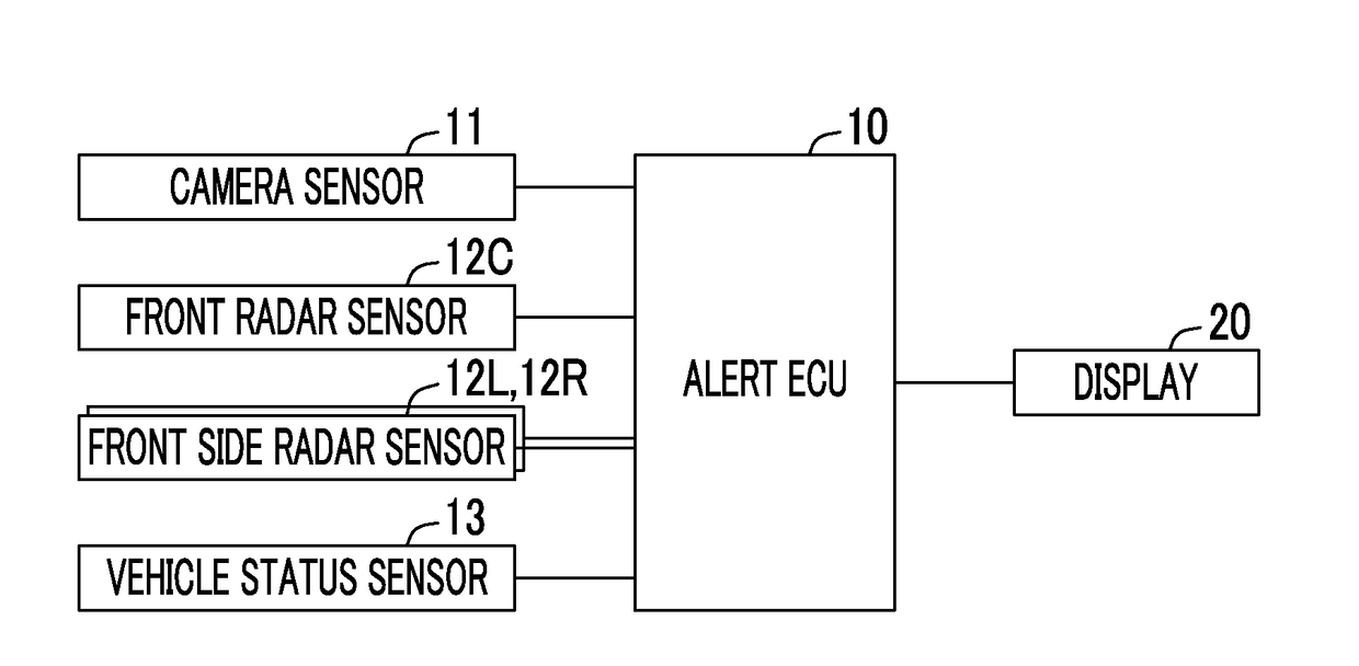
[0053]FIG. 1 is a schematic system configuration diagram of an in-vehicle alert apparatus according to a first embodiment of the present disclosure (hereinafter, referred to as a “first apparatus”). The first apparatus is an apparatus that is mounted in a vehicle and alerts a driver (operator) of the vehicle to an alert target (that is, an apparatus that provides alert for an alert target). The vehicle in which the in-vehicle alert apparatus is mounted is referred to as a “host vehicle” when the vehicle is distinguished from another vehicle. The first apparatus includes an alert ECU 10 (an example of an electronic control unit).

[0054]ECU is the abbreviation for “Electronic Control Unit” and includes a microcomputer as a main part. The microcomputer includes a CPU and a storage such as a ROM and a RAM. The CPU realizes various functions by executing instructions (programs and routines) stored in the ROM.

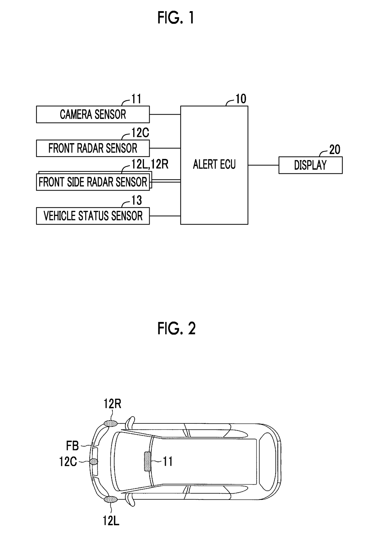
[0055]The first apparatus includes a camera sensor 11, a front radar sensor 12C, ...

second embodiment

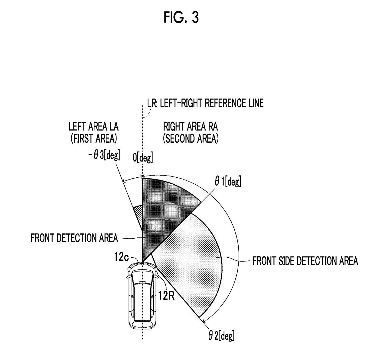
[0136]Next, an in-vehicle alert apparatus according to a second embodiment of the present disclosure (hereinafter, referred to as a “second apparatus”) will be described. The main difference between the second apparatus and the first apparatus is as follows. That is, as illustrated in FIG. 3, the second apparatus divides the area around the front of the host vehicle into the left area LA and the right area RA. The left area LA is an area on the left side of the right-left reference line LR that extends forward in the front-rear direction from the position of the center of the host vehicle in the vehicle width direction. The right area RA is an area on the right side of the right-left reference line LR. The second apparatus selects an obstacle having the shortest margin time period TTC among obstacles existing within the left area LA as an alert target for the left area LA. The second apparatus selects an obstacle having the shortest margin time period TTC among obstacles existing wi...

first modification example

of Second Apparatus

[0149]Next, a first modification example of the second apparatus will be described. The modification example is different from the second apparatus in that the modification example displays the second individual display screen 430 (refer to FIG. 8). Hereinafter, the difference will be mainly described. The modification example corresponds to the first modification example of the first apparatus.

[0150]Each time a predetermined time period elapses, the CPU of the modification example executes a routine illustrated in a flowchart in FIG. 13 instead of the routine illustrated in the flowchart in FIG. 12. The routine in FIG. 13 is a routine that displays the alert screen on the display 20. Among steps illustrated in FIG. 13, steps in which the same processes as the steps illustrated in FIG. 9 and FIG. 12 are performed will be designated by the same reference signs as the steps in FIG. 9 and FIG. 12. The steps will not be described in detail.

[0151]When the CPU makes a “...


PUM


Abstract

An in-vehicle alert apparatus includes an object information acquiring unit, a vehicle status information acquiring unit, a display unit, and an electronic control unit. The electronic control unit determines whether or not an alert target exists outside a field of view of a driver, and displays, as an alert screen, a single display screen when one alert target is selected, a whole display screen when two alert targets are selected and all of the two alert targets are determined to exist within the field of view of the driver, and an individual display screen when two alert targets are selected and an alert target having the highest alert degree is determined to exist outside the field of view of the driver.

Description

INCORPORATION BY REFERENCE[0001]The disclosure of Japanese Patent Application No. 2016-242913 filed on Dec. 15, 2016 including the specification, drawings and abstract is incorporated herein by reference in its entirety.BACKGROUND1. Technical Field[0002]The disclosure relates to an in-vehicle alert apparatus and an alert method that alert a driver to an alert target by using a display unit when an alert target to which the driver has to be alerted is detected around a host vehicle.2. Description of Related Art[0003]One of in-vehicle alert apparatuses in the related art (hereinafter, referred to as “an apparatus in the related art”) alerts a driver to an obstacle by displaying an object indication image that indicates an object existing around a host vehicle. Such an apparatus is suggested in, for example, Japanese Unexamined Patent Application Publication No. 2015-141490 (JP 2015-141490 A) (refer to paragraph 0023 to paragraph 0025, FIG. 4, and the like). The apparatus suggested in ...

Claims


Application Information

Patent Timeline
IPC IPC(8): B60Q9/00B60K35/00
CPCB60Q9/008B60K35/00B60K2350/1084B60R1/00B60R2300/8093B60K2370/152B60K2370/178B60K2370/179B60K2370/186B60K2370/193
Inventor OHTA, TEPPEI
Owner TOYOTA JIDOSHA KK
Why Eureka
Try Eureka