Vehicle control apparatus

a technology of control apparatus and control device, which is applied in the direction of mechanical apparatus, transportation and packaging, propulsion using engine-driven generators, etc., can solve the problems of generating a reduce the input torque prevent or reduce the shifting shock of the step-variable transmission

Active Publication Date: 2018-06-21
TOYOTA JIDOSHA KK
View PDF0 Cites 6 Cited by
  • Summary
  • Abstract
  • Description
  • Claims
  • Application Information

AI Technical Summary

Benefits of technology

[0012]According to the first mode of the invention, the required vehicle drive torque corresponding to the operation amount of the accelerator pedal is limited to the predetermined lower limit value, namely, is not lowered below the lower limit value, in the process of the power-on shift-up action. Therefore, the amount of reduction of the output torque of the drive power source to be controlled on the basis of the required vehicle drive torque and the amount of reduction of the input torque of the step-variable transmission are reduced even if the accelerator pedal is returned to the non-operated position in the process of the power-on shift-up action. Thus, the control apparatus according to the first mode of this invention is configured to reduce a risk of loss of the balance between the input torque of the step-variable transmission and the torque capacity of the relevant coupling device in the process of the power-on shift-up action. Accordingly, it is possible to prevent or reduce a shifting shock of the step-variable transmission due to reduction of the input torque of the step-variable transmission during its power-on shift-up action.
[0013]According to the second mode of the invention, the transmitted torque in the process of the power-on shift-up action of the selected coupling device is set at the value set on the basis of the required vehicle drive torque at a moment of initiation of the power-on shift-up action, even if the required vehicle drive torque is lowered from the above-indicated value in the process of the power-on shift-up action. Accordingly, the power-on shift-up action is progressively implemented in a smooth manner. Meanwhile, the required vehicle drive torque is limited to the predetermined lower limit value, even when the required vehicle drive torque is reduced, making it possible to reduce a risk of loss of the balance between the input torque of the step-variable transmission and the torque capacity of the selected coupling device in the process of the power-on shift-up action. Thus, the control apparatus assures not only smooth progressive implementation of the power-on shift-up action of the step-variable transmission, but also prevention or reduction of its shifting shock.
[0014]According to the third mode of the invention, the limitation of the required vehicle drive torque is terminated when the degree of progress of the power-on shift-up action has reached the predetermined value. Accordingly, the required vehicle drive torque is adequately limited during a period of time in which there is a risk of generation of the shifting shock of the step-variable transmission due to reduction of its input torque. In other words, the input torque of the step-variable transmission is controlled according to the non-limited required vehicle drive torque based on the operation amount of the accelerator pedal, after the risk of generation of the shifting shock has been sufficiently reduced.
[0015]According to the fourth mode of the invention, the predetermined lower limit of the required vehicle drive torque is set on the basis of a kind of the power-on shift-up action or a rotating speed of the input rotary member of the step-variable transmission. Accordingly, the control apparatus permits the power-on shift-up action to be adequately implemented, while preventing or reducing the shifting shock of the step-variable transmission due to reduction of the input torque of the step-variable transmission.
[0016]According to the fifth mode of the invention, the control apparatus is configured to control the vehicle provided with the engine and the motor / generator (second motor / generator) functioning as the drive power source, and the differential mechanism and the step-variable transmission disposed in series with each other. The control apparatus is configured to reduce the amount of reduction of the input torque of the step-variable transmission to be controlled on the basis of the required vehicle drive torque, even if the accelerator pedal is turned off in the process of the power-on shift-up action of the step-variable transmission. Thus, the control apparatus according to this fifth mode of the invention is configured to reduce the risk of loss of the balance between the input torque of the step-variable transmission and the torque capacity of the selected coupling device in the process of the power-on shift-up action. Accordingly, it is possible to prevent or reduce the shifting shock of the step-variable transmission due to reduction of the input torque of the step-variable transmission during its power-on shift-up action.

Problems solved by technology

In this case, there is a risk of generation of a shifting shock of the step-variable transmission due to a loss of balance between the input torque of the step-variable transmission and a torque capacity of its coupling devices.

Method used


Image

  • Vehicle control apparatus
  • Vehicle control apparatus
  • Vehicle control apparatus

Examples


first embodiment

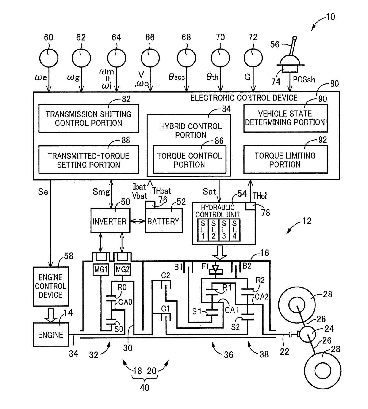
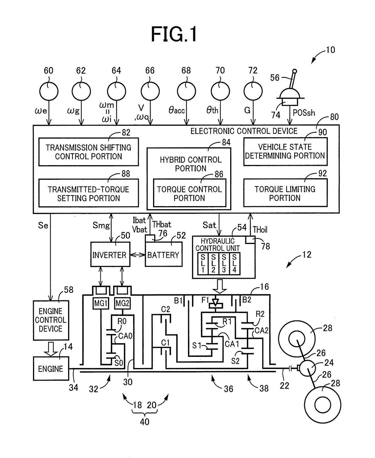
[0029]Reference is first made to FIG. 1, which is the schematic view showing an arrangement of a drive system 12 of a vehicle 10 to be controlled by a control apparatus according to the present invention, and major portions of the control apparatus to perform various controls of the vehicle 10. As shown in FIG. 1, the vehicular drive system 12 is provided with an engine 14 functioning as a drive power source, an electrically controlled continuously variable transmission portion 18 (hereinafter referred to as “continuously variable transmission portion 18”) connected directly or indirectly via a damper (not shown) or any other device to the engine 14, and a mechanically operated step-variable transmission portion 20 (hereinafter referred to as “step-variable transmission portion 20) connected to an output rotary member of the continuously variable transmission portion 18. The continuously variable transmission portion 18 and the step-variable transmission portion 20 are disposed in s...

second embodiment

[0084]In the preceding first embodiment, the control apparatus is configured to control the vehicle 10 provided with the continuously variable transmission portion 18 and the step-variable transmission portion 20 which are disposed in series with each other. However, the control apparatus according to the present invention may be configured to control a vehicle 100 shown in FIG. 10. The vehicle 100 which is controlled by the control apparatus in the form of a control device 122 according to a second embodiment is a hybrid vehicle provided with an engine 102 and a motor / generator MG functioning as the drive power source, and a power transmitting system 104. As shown in FIG. 10, the power transmitting system 104 includes a clutch KO, a torque converter 108 and a step-variable transmission 110, which are disposed within a stationary member in the form of a casing 106 fixed to a body of the vehicle 100, in this order of description as seen in the direction from the engine 102. The power...


PUM


Abstract

A control apparatus (80; 122) for a vehicle provided with a motor/generator (MG2; MG) functioning as a drive power source, and a step-variable transmission (20; 110) which constitutes a part of a power transmitting path between the drive power source and drive wheels (28; 116) and which is placed in a selected one of a plurality of speed positions with engagement of a selected one or ones of a plurality of coupling devices (CB). The control apparatus includes: a torque control portion (86) configured to control an output torque (Ti) of the drive power source (MG2) during a shifting action of the step-variable transmission (40; 110) from one of the speed positions to another of the speed positions, on the basis of a required vehicle drive torque (Tidem) corresponding to an operation amount (θacc) of an accelerator pedal, such that a value representing a state of a rotary motion of an input rotary member (30) of the step-variable transmission coincides with a target value; and a torque limiting portion (92) configured to limit the required vehicle drive torque to a predetermined lower limit value (Tif) in the process of a shift-up action of the step-variable transmission which is performed by placement of the accelerator pedal in an operated position.

Description

[0001]This application claims priority from Japanese Patent Application No. 2016-243616 filed on Dec. 15, 2016, the disclosure of which is herein incorporated by reference in its entirety.FIELD OF THE INVENTION[0002]The present invention relates to a control apparatus for a vehicle provided with a motor / generator and a step-variable transmission for transmitting a drive force of the motor / generator.BACKGROUND OF THE INVENTION[0003]There is well known a control apparatus for a vehicle provided with a motor / generator functioning as a drive power source, and a step-variable transmission which constitutes a part of a power transmitting path between the drive power source and drive wheels and which is placed in a selected one of a plurality of gear or speed positions with an engagement of a selected one or ones of a plurality of coupling devices. A hybrid vehicle disclosed in JP-2014-223888A is an example of this type of vehicle. This document discloses a control apparatus configured to ...

Claims


Application Information

Patent Timeline
Patent Type & Authority Applications(United States)
IPC IPC(8): B60W30/19B60W10/11B60W20/15B60L50/16
CPCB60W30/19B60W10/11B60W20/15B60W2540/10B60W2710/083B60K6/445B60K6/547B60W10/06B60W10/08B60W10/115B60W20/10B60W2710/0666B60L50/16B60K6/365F16H61/0437Y02T10/62Y02T10/72
Inventor TATSUSHIRO, HIROMASAKIMURA, HIROMICHIMATSUBARA, TOORUSHIIBA, KAZUYUKIKITAHATA, TAKESHISASADE, SHINICHIKOBAYASHI, NOBUFUSAYOSHIKAWA, MASATOKIMURA, TAKAHIRO
Owner TOYOTA JIDOSHA KK
Why Eureka
Try Eureka