Correction apparatus for angle sensor, and angle sensor

Active Publication Date: 2018-06-21
TDK CORPARATION
View PDF2 Cites 5 Cited by
  • Summary
  • Abstract
  • Description
  • Claims
  • Application Information

AI Technical Summary

Benefits of technology

[0011]It is an object of the present invention to provide a correction apparatus for an angle sensor and an angle sensor that enable reductio

Problems solved by technology

However, there are cases where the waveform of each detection signal is distorted from a sinusoidal curve.
A distortion of the waveform of each detection signal may resul

Method used


Image

  • Correction apparatus for angle sensor, and angle sensor
  • Correction apparatus for angle sensor, and angle sensor
  • Correction apparatus for angle sensor, and angle sensor

Examples


first embodiment

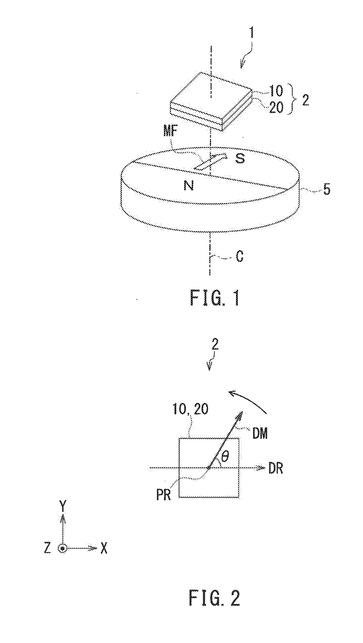
[0039]Preferred embodiments of the present invention will now be described in detail with reference to the drawings. First, reference is made to FIG. 1 to describe the general configuration of an angle sensor system including an angle sensor according to a first embodiment of the invention.

[0040]The angle sensor 1 according to the first embodiment is configured to generate a detected angle value θs having a correspondence with an angle θ to be detected. The angle sensor 1 according to the present embodiment is a magnetic angle sensor, in particular. As shown in FIG. 1, the angle sensor 1 according to the present embodiment detects a magnetic field MF whose direction rotates. In this case, the angle θ to be detected is the angle that the direction of the magnetic field MF at a reference position forms with respect to a reference direction. The angle sensor system shown in FIG. 1 includes the angle sensor 1, and a magnet 5 having a cylindrical shape, which is an example of means for g...

second embodiment

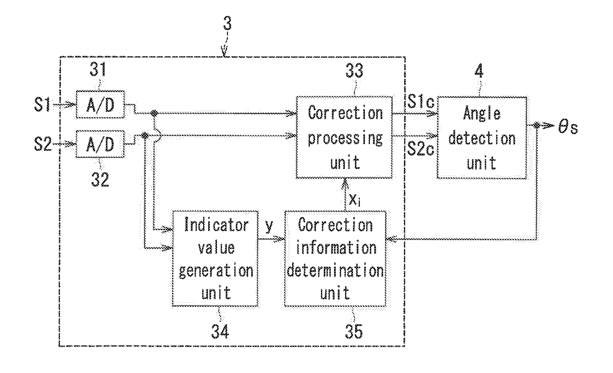
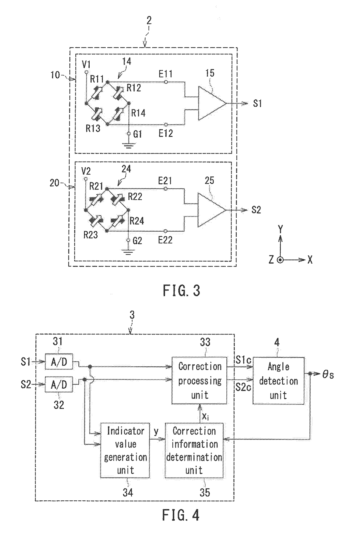
[0117]A second embodiment of the invention will now be described. First, the configuration of the correction apparatus according to the second embodiment will be described with reference to FIG. 15. The angle sensor 1 according to the second embodiment includes a correction apparatus 103 according to the second embodiment, in place of the correction apparatus 3 according to the first embodiment. FIG. 15 is a functional block diagram illustrating the configuration of the correction apparatus 103 and the angle detection unit 4. The correction apparatus 103 according to the second embodiment includes A / D converters 131 and 132, a correction processing unit 133, an indicator value generation unit 134, and a correction information determination unit 135.

[0118]The A / D converter 131 converts the first detection signal S1 into a digital signal. The A / D converter 132 converts the second detection signal S2 into a digital signal. The correction processing unit 133 convers the digital signals ...


PUM


Abstract

A correction apparatus for an angle sensor includes a correction processing unit, an indicator value generation unit, and a correction information determination unit. The correction processing unit performs correction processing on a plurality of detection signals to reduce an error of a detected angle value. The details of the correction processing are determined according to correction information. The indicator value generation unit generates, on the basis of the plurality of detection signals, an indicator value having a correspondence with the error of the detected angle value. The correction information determination unit generates an estimated indicator value using a function that takes one or more values each having a correspondence with the correction information as one or more variables, and determines the correction information by adaptive signal processing so as to reduce the difference between the indicator value and the estimated indicator value.

Description

BACKGROUND OF THE INVENTION1. Field of the Invention[0001]The present invention relates to a correction apparatus for correcting an error of an angle sensor that generates a detected angle value having a correspondence with an angle to be detected, and to an angle sensor including the correction apparatus.2. Description of the Related Art[0002]In recent years, angle sensors have been widely used in various applications, such as detection of the rotational position of a steering wheel or a power steering motor in an automobile. The angle sensors generate a detected angle value having a correspondence with an angle to be detected. Examples of the angle sensors include a magnetic angle sensor. A system using the magnetic angle sensor is typically provided with a magnetic field generation unit for generating a rotating magnetic field whose direction rotates in response to the rotation or linear movement of an object. The magnetic field generation unit is a magnet, for example. The angle...

Claims


Application Information

Patent Timeline
IPC IPC(8): G01D5/244G01D5/16
CPCG01D5/24476G01D5/16G01D5/14G01D5/243G01D18/00G01D5/145
Inventor MOCHIZUKI, SHINICHIROU
Owner TDK CORPARATION
Why Eureka
Try Eureka