Liquid crystal display device, driving method of the same, and electronic device including the same

a liquid crystal display and display device technology, applied in the direction of static storage, digital storage, instruments, etc., can solve the problems of short circuit between the gate and the source or the drain of the transistor, and achieve the suppression of the characteristic deterioration of the pull-up transistor, the reduction of the channel width of the transistor, and the suppression of the characteristic deterioration of the transistor

Active Publication Date: 2018-06-21
SEMICON ENERGY LAB CO LTD
View PDF6 Cites 0 Cited by
  • Summary
  • Abstract
  • Description
  • Claims
  • Application Information

AI Technical Summary

Benefits of technology

[0035]Further, there is no particular limitation on the kind of substrate for forming a transistor and a transistor can be formed using a variety of kinds of substrate. As an example of the substrate, a semiconductor substrate, a single crystal substrate (e.g., a silicon substrate), an SOI substrate, a glass substrate, a quartz substrate, a plastic substrate, a metal substrate, a stainless steel substrate, a substrate including a stainless steel foil, a tungsten substrate, a substrate including a tungsten foil, a flexible substrate, an attachment film, paper including a fibrous material, a base material film, or the like can be given. As an example of a glass substrate, a barium borosilicate glass substrate, an aluminoborosilicate glass substrate, soda lime glass substrate, or the like can be given. For a flexible substrate, a flexible synthetic resin such as plastics typified by polyethylene terephthalate (PET), polyethylene naphthalate (PEN), and polyether sulfone (PES), or acrylic can be used, for example. Examples of an attachment film are an attachment film formed using polypropylene, polyester, vinyl, polyvinyl fluoride, polyvinyl chloride, and the like. Examples of a base film are a base film formed using polyester, polyamide, polyimide, inorganic vapor deposition film, paper, and the like. Specifically, when a transistor is formed using a semiconductor substrate, a single crystal substrate, an SOI substrate, or the like, a transistor with few variations in characteristics, size, shape, or the like, high current supply capability, and a small size can be formed. By forming a circuit using such transistors, power consumption of the circuit can be reduced or the circuit can be highly integrated.
[0036]Note that the transistor may be formed using one substrate, and then, the transistor may be transferred to another substrate. Example of a substrate to which a transistor is transferred are, in addition to the above-described substrate over which the transistor can be formed, a paper substrate, a cellophane substrate, a stone substrate, a wood substrate, a cloth substrate (including a natural fiber (e.g., silk, cotton, or hemp), a synthetic fiber (e.g., nylon, polyurethane, or polyester), a regenerated fiber (e.g., acetate, cupra, rayon, or regenerated polyester), or the like), a leather substrate, a rubber substrate, and the like. When such a substrate is used, improvement in electrical characteristics of a transistor or reduction in power consumption of the transistor can be achieved. Further, improvement in reliability, improvement in heat resistance, reduction in weight, or reduction in thickness of a device which includes the transistor can be achieved.
[0037]Note that all the circuits which are necessary to realize a desired function can be formed using one substrate (e.g., a glass substrate, a plastic substrate, a single crystal substrate, or an SOI substrate). In this manner, cost can be reduced by reduction in the number of component parts or reliability can be improved by reduction in the number of connection to circuit components.
[0038]In addition, not all the circuits which are necessary to realize the predetermined function are needed to be formed using one substrate. That is, part of the circuits which are necessary to realize the predetermined function may be formed using one substrate and another part of the circuits which are necessary to realize the predetermined function may be formed using another substrate. For example, part of the circuits which are necessary to realize the predetermined function may be formed over a glass substrate and another part of the circuits which are necessary to realize the predetermined function may be formed using a single crystal substrate. Then, the single crystal substrate provided with the another part of the circuits which are necessary to realize the predetermined function may be connected to a glass substrate by COG (chip on glass) so that the single crystal substrate provided with the circuit (also referred to as an IC chip) can be provided for the glass substrate. Alternatively, the IC chip can be connected to the glass substrate by using TAB (tape automated bonding), COF (chip on film), SMT (surface mount technology), a printed substrate, or the like. When part of the circuits is formed over a substrate where a pixel portion is formed in this manner, cost can be reduced by reduction in the number of component parts or reliability can be improved by reduction in the number of connections between circuit components. Specifically, a circuit in a portion where a driving voltage is high, a circuit in a portion where a driving frequency is high, or the like consumes much power in many cases. Therefore, such a circuit is formed over a substrate (e.g., a single crystal substrate) which is different from a substrate over which the pixel portion is formed, so that an IC chip is formed. By the use of this IC chip, increase in power consumption can be prevented.
[0061]According to one embodiment of the present invention, deterioration in characteristics of a transistor can be suppressed. Alternatively, according to one embodiment of the present invention, the channel width of a transistor can be reduced. Particularly, suppression of deterioration in characteristics of a pull-up transistor or reduction in channel width of a pull-up transistor can be achieved. Alternatively, according to one embodiment of the present invention, a layout area can be reduced. Alternatively, according to one embodiment of the present invention, the size of a frame of a display device can be reduced. Alternatively, according to one embodiment of the present invention, a high-definition display device can be obtained. Alternatively, according to one embodiment of the present invention, an yield can be increased. Alternatively, according to one embodiment of the present invention, manufacturing costs can be reduced. Alternatively, according to one embodiment of the present invention, power consumption can be reduced. Alternatively, according to one embodiment of the present invention, current supply capability of an external circuit can be reduced. Alternatively, according to one embodiment of the present invention, the size of an external circuit or the size of a display device including the external circuit can be reduced.

Problems solved by technology

Alternatively, in some cases when the channel width of a transistor is large, a gate and a source or a drain of the transistor are likely to be short-circuited.

Method used


Image

  • Liquid crystal display device, driving method of the same, and electronic device including the same
  • Liquid crystal display device, driving method of the same, and electronic device including the same
  • Liquid crystal display device, driving method of the same, and electronic device including the same

Examples


embodiment 1

[0109]In this embodiment, one example of a semiconductor device will be described. The semiconductor device in this embodiment can be used for a variety of kinds of driver circuit, for example, a shift register, a gate driver, or a source driver. Note that the semiconductor device in this embodiment can also be referred to as a driver circuit or a circuit.

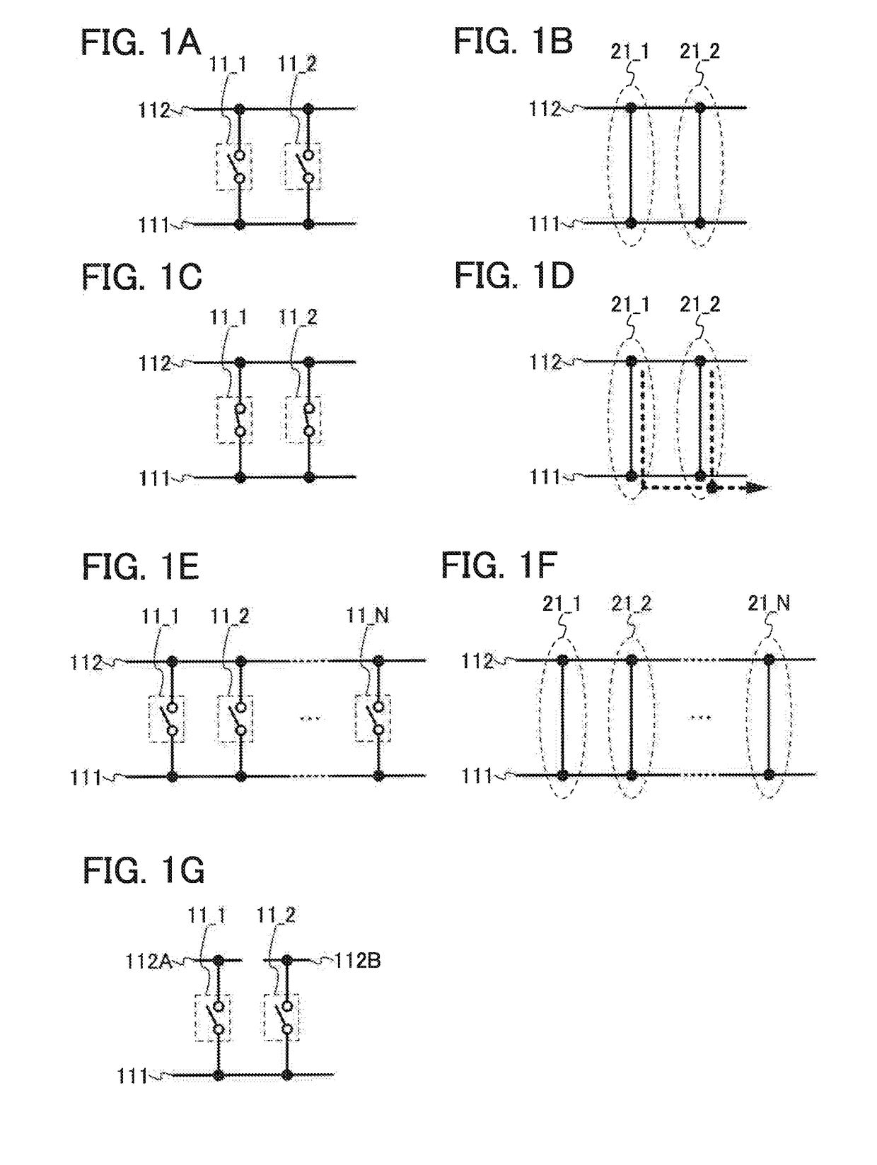
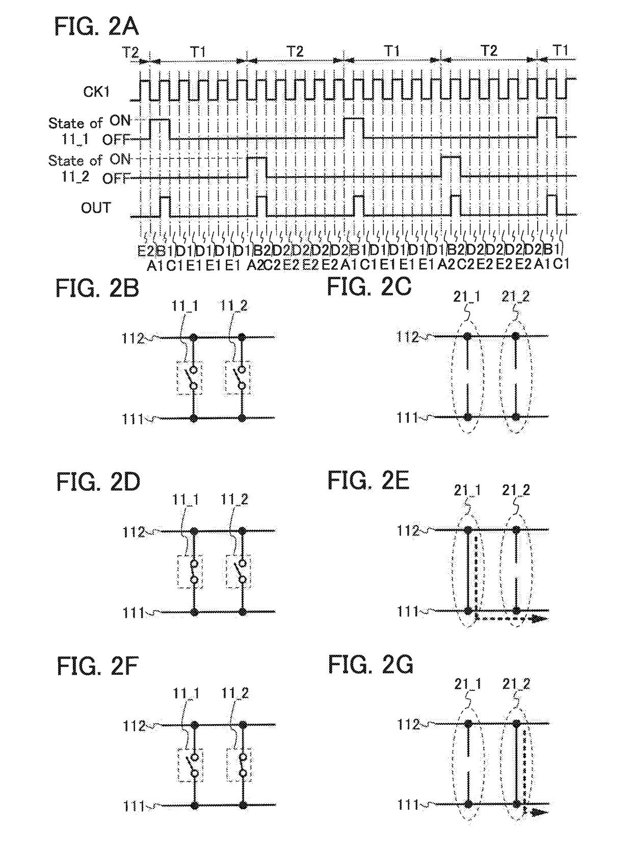
[0110]First, a semiconductor device of this embodiment will be described with reference to FIG. 1A. The semiconductor device in FIG. 1A includes a plurality of switches: switches 11_1 and 112. The switches 11_1 and 11_2 connects a wiring 111 and a wiring 112. However, this embodiment is not limited to this example. The semiconductor device can include three or more switches.

[0111]Next, an example of a signal, voltage, or the like which is input to or output from each wiring is described.

[0112]As an example, a signal OUT is output from the wiring 111. The signal OUT can have a first potential state and a second potential state, for ...

embodiment 2

[0151]In this embodiment, an example of a semiconductor device is described. The semiconductor device in this embodiment can include the semiconductor device described in Embodiment 1. Specifically, a structure in the case where, for example, a transistor is used as a switch included in the semiconductor device in Embodiment 1 is described. However, this embodiment is not limited to this example. A variety of elements, a variety of circuits, or the like can be used as a switch. Note that description of the content described in Embodiment 1 is omitted. Note that the content described in this embodiment can be combined with the content described in Embodiment 1 as appropriate.

[0152]First, the semiconductor device of this embodiment will be described with reference to FIG. 4A. The semiconductor device in FIG. 4 includes a circuit 100. The circuit 100 has a structure similar to that in the case where a transistor is used as a switch in the structure described in Embodiment 1. FIG. 4A sh...

embodiment 3

[0243]In this embodiment, an example of a structure which is different from that of the circuit 10 described in Embodiment 2 is described. Note that description of the content in Embodiments 1 and 2 is omitted. Note that the content described in this embodiment can be combined with the content described in Embodiments 1 and 2 as appropriate.

[0244]First, a specific example of the circuit 10 which is different from that in Embodiment 2 is described with reference to FIG. 14. The circuit 10 in FIG. 14 includes a circuit 300 in addition to the circuit 200. The circuit 300 is part of the circuit 10. Note that part of the circuit 300 can be used also as part of the circuit 200. Part of the circuit 200 can be used also as part of the circuit 300. The circuit 300 is connected to the wiring 113, the wiring 116, the wiring 117, the node n1, the node n2, and / or the wiring 111. However, this embodiment is not limited to this example. The circuit 200 can be connected to a variety of wirings or n...


PUM


Abstract

It is an object to suppress deterioration of characteristics of a transistor in a driver circuit. A first switch for controlling whether to set a potential state of an output signal by being turned on and off in accordance with the first input signal, and a second switch for controlling whether to set a potential state of an output signal by being turned on and off in accordance with the second input signal are included. A first wiring and a second wiring are brought into electrical continuity by turning on and off of the first switch or the second switch.

Description

CROSS-REFERENCE TO RELATED APPLICATIONS[0001]This application is a continuation of U.S. application Ser. No. 12 / 731,203, filed Mar. 25, 2010, now pending, which claims the benefit of a foreign priority application filed in Japan as Serial No. 2009-077200 on Mar. 26, 2009, both of which are incorporated by reference.BACKGROUND OF THE INVENTION1. Field of the Invention[0002]The present invention relates to a semiconductor device, a display device, a liquid crystal display device, a method for driving these devices, and a method for manufacturing these devices. The present invention particularly relates to a semiconductor device, a display device, and a liquid crystal display device which include driver circuits formed over the same substrates as pixel portions, and a method for driving these devices. Further, the present invention relates to an electronic device including the semiconductor device, the display device, or the liquid crystal display device.2. Description of the Related A...

Claims


Application Information

Patent Timeline
Patent Type & Authority Applications(United States)
IPC IPC(8): G09G3/36G11C19/28
CPCG11C19/28G09G2320/043G09G3/3677G09G2300/0417G09G3/3688G09G2310/0286G09G3/3266G09G2310/0267G09G2330/021
Inventor KIMURA, HAJIMEUMEZAKI, ATSUSHI
Owner SEMICON ENERGY LAB CO LTD
Why Eureka
Try Eureka