Liquid crystal display device, driving method of the same, and electronic device including the same
- Summary
- Abstract
- Description
- Claims
- Application Information
AI Technical Summary
Benefits of technology
Problems solved by technology
Method used
Image
Examples
embodiment 1
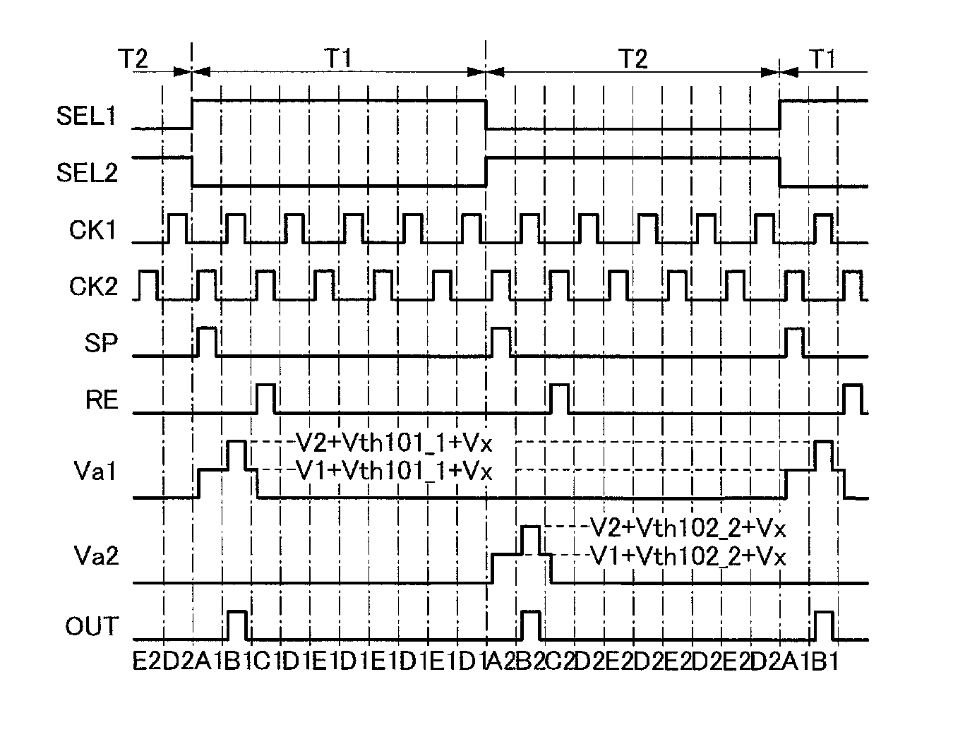
[0109]In this embodiment, one example of a semiconductor device will be described. The semiconductor device in this embodiment can be used for a variety of kinds of driver circuit, for example, a shift register, a gate driver, or a source driver. Note that the semiconductor device in this embodiment can also be referred to as a driver circuit or a circuit.
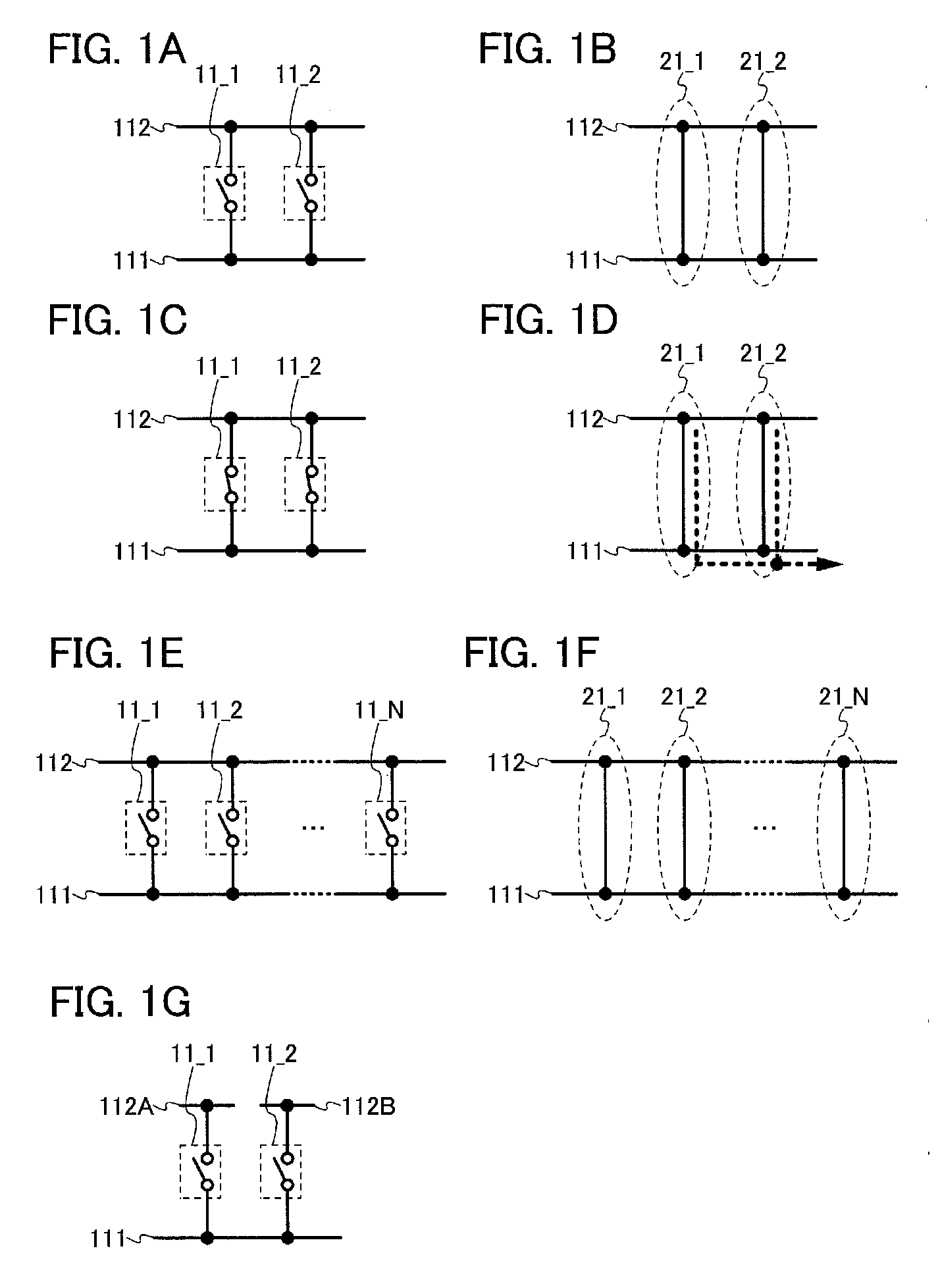
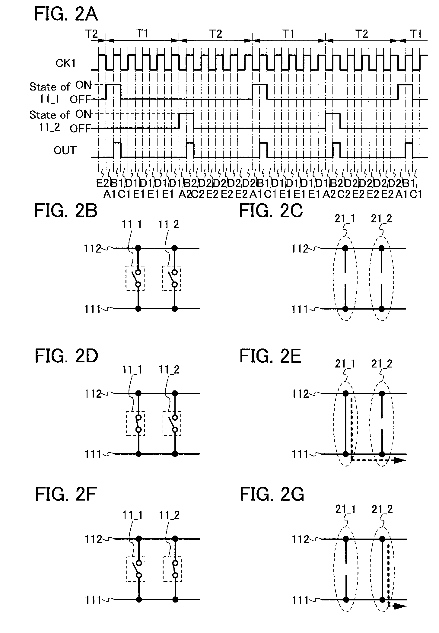
[0110]First, a semiconductor device of this embodiment will be described with reference to FIG. 1A. The semiconductor device in FIG. 1A includes a plurality of switches: switches 11_1 and 11_2. The switches 11_1 and 11_2 connects a wiring 111 and a wiring 112. However, this embodiment is not limited to this example. The semiconductor device can include three or more switches.
[0111]Next, an example of a signal, voltage, or the like which is input to or output from each wiring is described.
[0112]As an example, a signal OUT is output from the wiring 111. The signal OUT can have a first potential state and a second potential state, for...
embodiment 2
[0151]In this embodiment, an example of a semiconductor device is described. The semiconductor device in this embodiment can include the semiconductor device described in Embodiment 1. Specifically, a structure in the case where, for example, a transistor is used as a switch included in the semiconductor device in Embodiment 1 is described. However, this embodiment is not limited to this example. A variety of elements, a variety of circuits, or the like can be used as a switch. Note that description of the content described in Embodiment 1 is omitted. Note that the content described in this embodiment can be combined with the content described in Embodiment 1 as appropriate.
[0152]First, the semiconductor device of this embodiment will be described with reference to FIG. 4A. The semiconductor device in FIG. 4 includes a circuit 100. The circuit 100 has a structure similar to that in the case where a transistor is used as a switch in the structure described in Embodiment 1. FIG. 4A sh...
embodiment 3
[0243]In this embodiment, an example of a structure which is different from that of the circuit 10 described in Embodiment 2 is described. Note that description of the content in Embodiments 1 and 2 is omitted. Note that the content described in this embodiment can be combined with the content described in Embodiments 1 and 2 as appropriate.
[0244]First, a specific example of the circuit 10 which is different from that in Embodiment 2 is described with reference to FIG. 14. The circuit 10 in FIG. 14 includes a circuit 300 in addition to the circuit 200. The circuit 300 is part of the circuit 10. Note that part of the circuit 300 can be used also as part of the circuit 200. Part of the circuit 200 can be used also as part of the circuit 300. The circuit 300 is connected to the wiring 113, the wiring 116, the wiring 117, the node n1, the node n2, and / or the wiring 111. However, this embodiment is not limited to this example. The circuit 200 can be connected to a variety of wirings or n...
PUM
 Abstract
Description
Claims
Application Information
 - R&D
- Intellectual Property
- Life Sciences
- Materials
- Tech Scout
- Unparalleled Data Quality
- Higher Quality Content
- 60% Fewer Hallucinations
Browse by: Latest US Patents, China's latest patents, Technical Efficacy Thesaurus, Application Domain, Technology Topic, Popular Technical Reports.
© 2025 PatSnap. All rights reserved.Legal|Privacy policy|Modern Slavery Act Transparency Statement|Sitemap|About US| Contact US: help@patsnap.com


