Thermoelectric conversion module

a conversion module and thermoelectric technology, applied in the direction of thermoelectric devices with peltier/seeback effect, thermoelectric device junction materials, etc., can solve the problems of low power generation output of the entire thermoelectric conversion device, inability to easily generate differences, and inability to generate differences easily. achieve the effect of high power generation outpu

Inactive Publication Date: 2018-06-21
FUJIFILM CORP
View PDF3 Cites 15 Cited by
  • Summary
  • Abstract
  • Description
  • Claims
  • Application Information

AI Technical Summary

Benefits of technology

[0022]According to the present invention, it is possible to obtain a ther

Problems solved by technology

However, in the configuration described in JP2006-86510A, since the low thermal conductive base materials of polyimide or the like are overlapped, a temperature difference is not easily generated in the overlapped thermoelectric conversion elements at the center of the base materials and thus the power generation amount of the entire thermoelectric conversion device is decreased.
In addition, since it is required to use resin for reinforcement between the overlapped thermoelectric conversion ele

Method used


Image

  • Thermoelectric conversion module
  • Thermoelectric conversion module
  • Thermoelectric conversion module

Examples


first example

[0213]Hereinafter, the features of the present invention will be further specifically described with reference to the following examples. The materials, reagents, used amounts, amounts of substances, ratios, treatment contents, treatment procedures, and the like shown in the following examples can be appropriately changed without departing from the scope of the present invention. Therefore, the following specific examples are to be considered in all respects as illustrative and not restrictive.

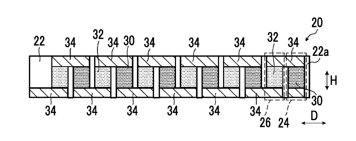
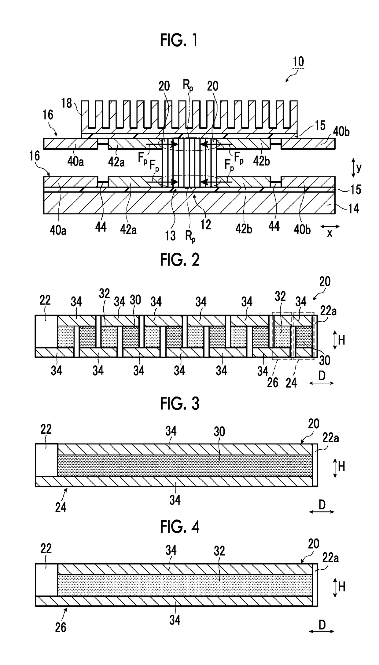
[0214]In a first example, basically, the configuration of the thermoelectric conversion device 10 shown in FIG. 1 was used.

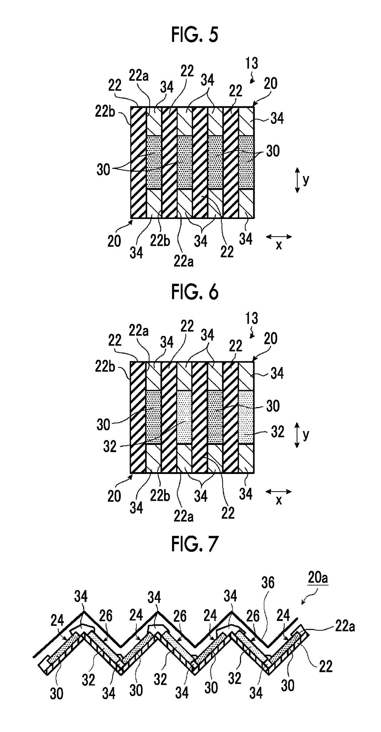
[0215]A thermoelectric conversion module body 13 in which fifty thermoelectric conversion module substrates 20 shown in FIG. 2 were overlapped such that the direction of the insulating substrate 22 and the direction of the connection electrode 34 were aligned and the thermoelectric conversion elements faced the rear surface 22b of the insulating substrate 22 to avoid direc...

example 1

[0241]Example 1 was configured such that in the configuration of the thermoelectric conversion device 10 shown in FIG. 1, the heat transfer portion was provided on only the high temperature side of the thermoelectric conversion module body.

example 2

[0242]Example 2 was configured such that in the configuration of the thermoelectric conversion device 10 shown in FIG. 1, the heat transfer portion was provided on only the low temperature side of the thermoelectric conversion module body.


PUM


Abstract

A thermoelectric conversion module includes a thermoelectric conversion module body which includes a plurality of thermoelectric conversion module substrates in which at least one of a P-type thermoelectric conversion element having a P-type thermoelectric conversion layer and a pair of connection electrodes which are electrically connected to the P-type thermoelectric conversion layer, or an N-type thermoelectric conversion element having an N-type thermoelectric conversion layer and a pair of connection electrodes which are electrically connected to the N-type thermoelectric conversion layer is provided on one surface of an insulating substrate having flexibility, the plurality of thermoelectric conversion module substrates being arranged such that a direction of the connection electrode and a direction of the insulating substrate are aligned, and a heat transfer portion which is provided on a side of the thermoelectric conversion module body close to at least one connection electrode of the thermoelectric conversion module substrate, presses the thermoelectric conversion module substrate in an arrangement direction, and transfers heat to the thermoelectric conversion module body or dissipates heat of the thermoelectric conversion module body. A thermal conductivity of the heat transfer portion is 10 W/mK or higher. A normal stress in a direction perpendicular to a surface of the insulating substrate in a case of pressing the thermoelectric conversion module substrate in the arrangement direction by the heat transfer portion is 0.01 MPa or higher.

Description

CROSS-REFERENCE TO RELATED APPLICATIONS[0001]This application is a Continuation of PCT International Application No. PCT / JP2016 / 072078 filed on Jul. 27, 2016, which claims priority under 35 U.S.C. § 119(a) to Japanese Patent Application No. 2015-170568 filed on Aug. 31, 2015 and Japanese Patent Application No. 2016-108549 filed on May 31, 2016. Each of the above applications is hereby expressly incorporated by reference, in its entirety, into the present application.BACKGROUND OF THE INVENTION1. Field of the Invention[0002]The present invention relates to a thermoelectric conversion module formed using a flexible insulating substrate and particularly relates to a thermoelectric conversion module exhibiting high power generation output.2. Description of the Related Art[0003]As a device capable of directly generating electricity from a temperature difference, a thermoelectric conversion device is known.[0004]The defect of a thermoelectric conversion device having a thermoelectric conv...

Claims


Application Information

Patent Timeline
IPC IPC(8): H01L35/32H01L35/30H01L35/22
CPCH01L35/32H01L35/30H01L35/22H10N10/855H10N10/856H10N10/17H10N10/13
Inventor IMAI, SHINJISUZUKI, HIDEYUKI
Owner FUJIFILM CORP
Why Eureka
Try Eureka