Shift control device and shift control method for hybrid vehicle

Active Publication Date: 2018-06-28
TOYOTA JIDOSHA KK
View PDF0 Cites 4 Cited by
  • Summary
  • Abstract
  • Description
  • Claims
  • Application Information

AI Technical Summary

Benefits of technology

The patent describes a shift control device for a hybrid vehicle that can improve fuel efficiency and prevent deterioration in drivability when switching between different traveling modes. The device uses a multi-stage automatic transmission with a combination of planetary gear trains and frictional engaging elements, an internal combustion engine, and a rotating electric machine. The device sets a gear ratio for each mode based on the efficiency of the rotating electric machine and the internal combustion engine. This allows for a more efficient gear ratio in the EV traveling mode to improve fuel efficiency. The device also includes a shift control method that prevents abrupt shifts and maintains a smooth driving experience. Overall, the device improves the performance and efficiency of the hybrid vehicle.

Problems solved by technology

In addition, in the EV traveling mode, the rotating electric machine needs to have remaining power to start the internal combustion engine at all times and maximum output to the drive wheels is limited in the high-rotation region and the low-rotation region of the rotating electric machine.
Furthermore, when the traveling mode is switched between the HV traveling mode and the EV traveling mode and there is excessive divergence between selected gear ratios along with the switching, an excessive shift shock occurs.
However, since the EV traveling mode and the regenerative traveling mode are not different from each other in most efficient rotation speed of the rotating electric machine, the upshifting operation being performed may result in a decrease in fuel efficiency.
In addition, in a case where a driver's stepping-on amount with respect to the accelerator pedal is further increased, the internal combustion engine may be started along with downshifting or switching to the HV traveling mode and there is a possibility of deterioration in drivability.
In addition, in a case where the engine needs to be started or stopped at the same time as switching between the traveling regions, there is further deterioration in drivability due to a rapid change in gear ratio.

Method used


Image

  • Shift control device and shift control method for hybrid vehicle
  • Shift control device and shift control method for hybrid vehicle
  • Shift control device and shift control method for hybrid vehicle

Examples


Embodiment Construction

[0027]An embodiment of a shift control device for a hybrid vehicle according to an aspect of the disclosure will be described in detail with reference to FIGS. 1 to 6. However, the aspect of the disclosure is not limited to the embodiment and can be applied to every shift control device for a hybrid vehicle that includes a configuration as described in at least claim 1 out of claims.

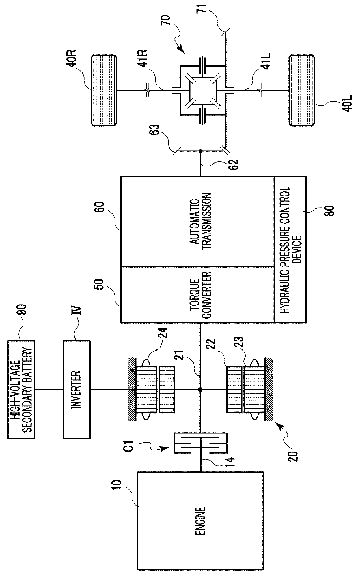
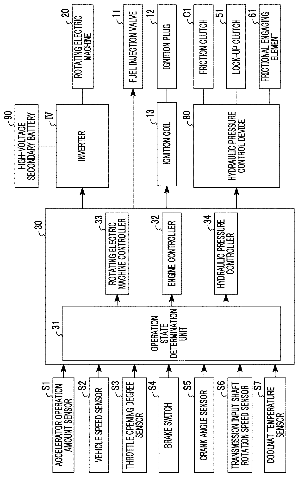
[0028]FIG. 1 schematically illustrates a schematic configuration of a hybrid vehicle in the embodiment and FIG. 2 illustrates a control block of main components in the embodiment illustrated in FIG. 1. In the hybrid vehicle in the embodiment, one engine 10 and one rotating electric machine 20 are installed as prime movers and the engine 10 is a spark-ignition direct injection internal combustion engine in which fuel is directly injected to a combustion chamber (not shown) from a fuel injection valve 11. However, the aspect of the disclosure is not limited to this. The amount of fuel supplied to the combu...


PUM


Abstract

A shift control device is configured to control switching between shift stages in a multi-stage automatic transmission such that a gear ratio selected at a predetermined vehicle speed and selected in a regenerative traveling mode that is a boundary region with respect to an EV traveling mode becomes greater than a gear ratio selected at the predetermined vehicle speed and selected in an HV traveling mode that is a boundary region with respect to the EV traveling mode, and is configured to control the switching between the shift stages such that a gear ratio of a shift stage selected when the traveling mode is switched from the regenerative traveling mode to the EV traveling mode is greater than a gear ratio of a shift stage selected when the traveling mode is switched from the HV traveling mode to the EV traveling mode under the same vehicle speed and parameter.

Description

INCORPORATION BY REFERENCE[0001]The disclosure of Japanese Patent Application No. 2016-251167 filed on Dec. 26, 2016 including the specification, drawings and abstract is incorporated herein by reference in its entirety.BACKGROUND1. Technical Field[0002]The disclosure relates to a shift control device for a hybrid vehicle in which a multi-stage automatic transmission is installed and a shift control method.2. Description of Related Art[0003]A deceleration energy regenerating system, in which a portion of kinetic energy that is wasted as thermal energy is recovered as pressure energy when a vehicle decelerates while traveling and the pressure energy is used at the time of acceleration of the vehicle, has been proposed in Japanese Unexamined Patent Application Publication No. 10-103111 (JP 10-103111 A). In JP 10-103111 A, in a case where an engine that is in a stopped state at the time of regeneration of kinetic energy is started with a regenerating process of the kinetic energy being...

Claims


Application Information

Patent Timeline
IPC IPC(8): B60W20/30B60W10/11F16H61/02
CPCB60W20/30B60W10/11F16H61/0213F16H59/44B60Y2200/92Y10S903/945B60W20/00B60W30/182B60K6/48B60K2006/4825B60W10/06B60W10/08B60W30/18127B60W2050/0075B60W2540/10B60W2710/1005B60Y2300/18125F16H2061/0227F16H2061/0234Y02T10/62
Inventor KUWAHARA, SEIJISUZUKI, YUSUKENAKANISHI, NAOKIUSUI, KUNIHIKO
Owner TOYOTA JIDOSHA KK
Why Eureka
Try Eureka