Exhaust turbine power generating system and control device for the same

a technology of exhaust turbine and power generation system, which is applied in the direction of engines, mechanical equipment, machines/engines, etc., can solve the problems of reducing the opportunity for electric power generation, difficult to maintain the turbine rotation rate at an appropriate rotation, and small exhaust energy that is input to the turbine during the period between a period of the next blowdown stream, so as to effectively suppress the decrease of the turbine rotation rate and reduce the effect of exhaust energy

Inactive Publication Date: 2018-09-13
TOYOTA JIDOSHA KK
View PDF0 Cites 2 Cited by
  • Summary
  • Abstract
  • Description
  • Claims
  • Application Information

AI Technical Summary

Benefits of technology

[0009]More specifically, the electronic control unit individually controls the first electric power generation load in the first period and the second electric power generation load in the second period such that the second electric power generation load becomes equal to or smaller than the first electric power generation load. With electric power generation load control as described above, it is possible to effectively suppress a decrease in turbine rotation rate in the second period in which the exhaust energy is relatively small. As a result, it is easy to maintain the turbine rotation rate at an appropriate rotation rate and to continuously perform appropriate electric power generation.
[0010]Particularly, since it is possible to effectively suppress a decrease in turbine rotation rate even in a case where the absolute value of the exhaust energy is further smaller and there is no significant increase in turbine rotation rate, it is possible to maintain the turbine rotation rate at an appropriate rotation rate. The above-described fact means expansion of an engine operating region suitable for electric power generation. The electric power generation opportunity is increased due to the expansion of the engine operating region suitable for electric power generation.

Problems solved by technology

However, exhaust energy that is input to the turbine during a period between a period of the blowdown stream and a period of the next blowdown stream is relatively small.
In other words, it becomes difficult to maintain the turbine rotation rate at an appropriate rotation rate for appropriate electric power generation.
However, a limit on an engine operating region suitable for electric power generation means a decrease in electric power generation opportunity, which is not preferable.

Method used


Image

  • Exhaust turbine power generating system and control device for the same
  • Exhaust turbine power generating system and control device for the same
  • Exhaust turbine power generating system and control device for the same

Examples


Embodiment Construction

[0027]An embodiment of the disclosure will be described with reference to attached drawings.

1. Configuration of Exhaust Turbine Power Generating System

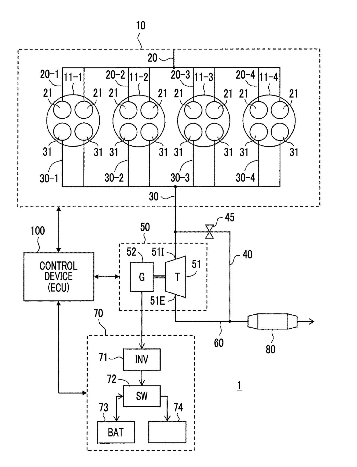
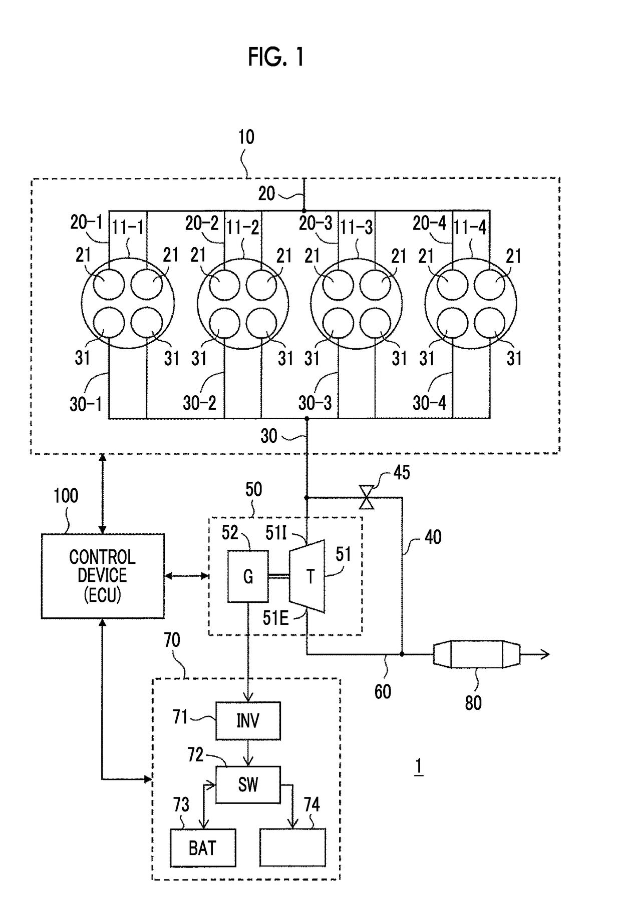
[0028]FIG. 1 is a schematic diagram illustrating an example of the configuration of an exhaust turbine power generating system 1 according to the embodiment of the disclosure. The exhaust turbine power generating system 1 includes an internal combustion engine 10 (engine), an exhaust turbine power generator 50, an electric device 70, and a control device 100 as main components.

[0029]The internal combustion engine 10 includes cylinders 11 (combustion chamber) in which combustion is performed. Although four cylinders 11-1, 11-2, 11-3, 11-4 are illustrated in FIG. 1, the number of the cylinders 11 is optional. In each cylinder 11, a piston (not shown) is provided such that the piston can reciprocate vertically. The vertical reciprocating motion of the piston results in intake and exhaust.

[0030]An intake pipe 20 (intake port) is provided ...


PUM


Abstract

An exhaust turbine power generating system includes an internal combustion engine, an exhaust turbine power generator, and an electronic control unit configured to individually control a first electric power generation load of the exhaust turbine power generator in a first period and a second electric power generation load of the exhaust turbine power generator in a second period and to perform control such that the second electric power generation load of the exhaust turbine power generator becomes equal to or smaller than the first electric power generation load. The first period is a period that starts at an exhaust start timing in an exhaust cycle and the second period is a period after the first period in the exhaust cycle. The exhaust start timing is a timing at which the exhaust gas starts to be discharged toward the turbine from an arbitrary cylinder in the internal combustion engine.

Description

INCORPORATION BY REFERENCE[0001]The disclosure of Japanese Patent Application No. 2017-042824 filed on Mar. 7, 2017 including the specification, drawings and abstract is incorporated herein by reference in its entirety.BACKGROUND1. Technical Field[0002]The disclosure relates to an exhaust turbine power generating system that performs electric power generation by using exhaust energy from an internal combustion engine and relates to a control device for an exhaust turbine power generating system.2. Description of Related Art[0003]Japanese Unexamined Patent Application Publication No. 2015-21448 (JP 2015-21448 A) discloses an exhaust turbine power generating system that performs electric power generation by using exhaust energy of an internal combustion engine. An exhaust gas flow path in the exhaust turbine power generating system is divided into two systems. Exhaust gas in a blowdown stream is supplied to a turbine unit in an exhaust turbine power generator through a first exhaust g...

Claims


Application Information

Patent Timeline
Patent Type & Authority Applications(United States)
IPC IPC(8): F02B37/12F01N5/04F02B39/16
CPCF02B37/12F01N5/04F02B39/16F05B2220/602F05B2220/706F01N3/10F01N2340/06Y02T10/12
Inventor YOEDA, KEIJI
Owner TOYOTA JIDOSHA KK
Why Eureka
Try Eureka