Distributed indoor smart antenna system for over-the-air television reception

a technology of smart antennas and distributed indoors, applied in the field of smart antenna systems, can solve the problems of limited broadcast range of the system, own limitations, and generally rather expensive, and achieve the effect of increasing signal quality

Active Publication Date: 2018-06-28
DISH TECH L L C
View PDF4 Cites 9 Cited by
  • Summary
  • Abstract
  • Description
  • Claims
  • Application Information

AI Technical Summary

Benefits of technology

[0013]The present disclosure is direct towards a distributed indoor antenna system for over-the-air television reception that includes technological improvements that increase signal quality on a display device. The distributed indoor antenna system uses multiple distributed antenna nodes that are placed and oriented at various spaced-apart locations around a user's residence or other location of interest. In one embodiment, each of the multiple distributed antenna nodes includes an antenna that receives broadcast signals, a tuner that decodes the broadcast signals, and a Wi-Fi converter that changes the decoded broadcast signals into a format that enables Wi-Fi transmission. A reception gateway receives the signals from the multiple distributed antenna nodes and sends a retransmission signal to the display device. The retransmission signal may be a signal or signal combination, as determined by the reception gateway. The display device may be selected from wireless devices such as smartphones and tablets, or may be a wired device such as a large screen television.

Problems solved by technology

For example, over-the-air television is generally free, but is limited to the broadcast range of the system and which may be affected by the terrain between the receiving antenna and the broadcast tower.
While satellite and cable television may be accessed at great distances from the distributor, they are generally rather expensive and may have their own limitations as well (e.g., weather).
Unfortunately, hills, mountains, great distances, and other obstacles can lead to poor reception of over-the-air television signals.
As a result, the viewer may be unable to receive over-the-air television or the received signals may be insufficient to provide a usable image to the viewer.
Over-the-air digital TV reception is often unreliable, particularly indoors.
Problems include weak signal coverage, diverse locations of the TV transmission towers, and limitations affecting optimal location of the receiving antenna.
Installing an outdoor over-the-air antenna is not desirable for average consumers.
Specialized tools and techniques are required that are not readily available.
Additionally, confirming that a reliable set of signals within a desired margin have been achieved may only be determined by specialized RF testing equipment and the knowledge to use them.
Notably, a high number of consumers are unsatisfied with the reception received using indoor antennas since over-the-air digital TV indoor antennas introduce a host of new potential reception inhibiting factors that were not anticipated in the planning for digital TV coverage and reception.
These inhibiting factors include: (1) a weaker signal due to attenuation (loss) through a building's outside walls, (2) uncontrolled bouncing of signals within the room where the indoor antenna is located, and (3) interference with other electronic devices in a residence (building, other structure, or the like) in which the indoor antenna is located.
Multipath is a variable of many factors and is difficult to predict or correct when it is severe.
However, these advanced antenna and receiver design techniques also have disadvantages as well.
This is often not possible or practical if the home does not have a window facing the general direction of the local TV broadcast towers.
Additionally, if the central TV viewing location is on the first floor of a residence, placing the indoor over-the-air antenna in a second floor window and cabling to the central TV location on the first floor is a difficult and expensive endeavor.
Another challenge with indoor over-the-air antennas is the inability to receive all the available broadcast TV stations from a single antenna location.
An example of this difficulty is when an antenna is only able to receive one particular TV station in one room, while only able to receive another particular TV station in another room.

Method used


Image

  • Distributed indoor smart antenna system for over-the-air television reception
  • Distributed indoor smart antenna system for over-the-air television reception
  • Distributed indoor smart antenna system for over-the-air television reception

Examples


Embodiment Construction

[0028]Persons of ordinary skill in the art will understand that the present disclosure is illustrative only and not in any way limiting. Other embodiments and various combinations of the presently disclosed system and method readily suggest themselves to such skilled persons having the assistance of this disclosure.

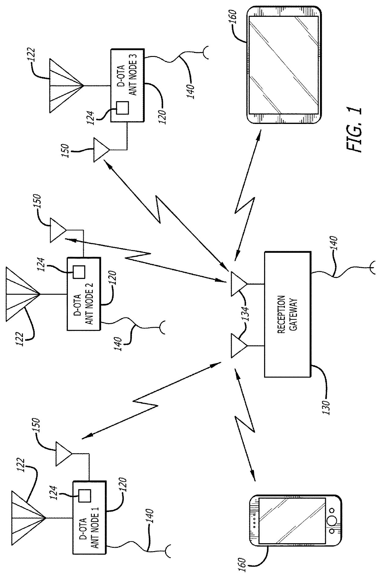
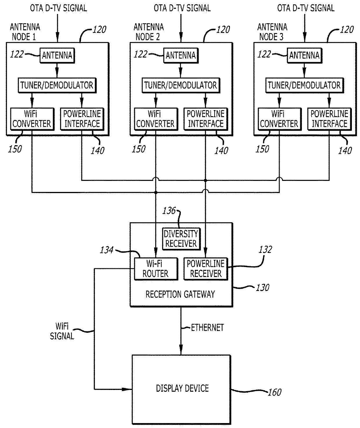
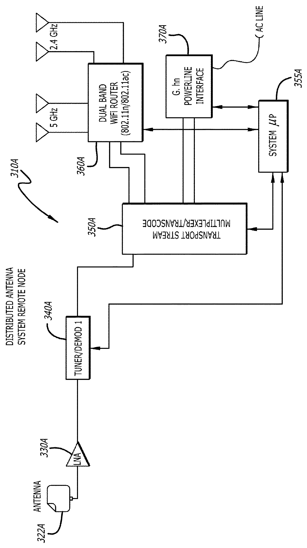
[0029]Each of the features and teachings disclosed herein can be utilized separately or in conjunction with other features and teachings to provide a distributed indoor smart antenna system for over-the-air digital television reception. Representative examples utilizing many of these additional features and teachings, both separately and in combination, are described in further detail with reference to attached FIGS. 1-5. This detailed description is intended to teach a person of skill in the art further details for practicing aspects of the present teachings and is not intended to limit the scope of the claims. Therefore, combinations of features disclosed above in the d...


PUM


Abstract

A distributed indoor antenna system for over-the-air television reception includes technological improvements that increase signal quality on a display device. The system includes a plurality of active distributed antenna nodes and a reception gateway. The distributed antenna nodes are placed and oriented at various spaced-apart locations around a user's residence or other location of interest. Each of the plurality of active distributed antenna nodes includes an antenna, a demodulator, and a Wi-Fi converter. The plurality of active distributed antenna nodes receives the broadcast signals, decodes the broadcast signals, and transcodes the decoded broadcast signals into a Wi-Fi signal format. The reception gateway receives the transcoded broadcast signals and determines which signal or which signal combination to retransmit to the display device.

Description

BACKGROUNDTechnical Field[0001]The present disclosure relates generally to a smart antenna system, and more particularly, but not exclusively, to a distributed indoor smart antenna system for over-the-air television reception.Description of the Related Art[0002]Content distributors deliver audiovisual content to users through a variety of different systems. These systems may include over-the-air broadcast television, satellite television, and cable television. Each of these systems has advantages and disadvantages. For example, over-the-air television is generally free, but is limited to the broadcast range of the system and which may be affected by the terrain between the receiving antenna and the broadcast tower. While satellite and cable television may be accessed at great distances from the distributor, they are generally rather expensive and may have their own limitations as well (e.g., weather).[0003]Many people are unwilling to pay monthly service fees to a satellite or cable...

Claims


Application Information

Patent Timeline
Patent Type & Authority Applications(United States)
IPC IPC(8): H04N21/4402H04N21/4363H04N21/426H04L12/66H04B7/08H04N21/438
CPCH04N21/440218H04N21/43637H04N21/4382H04L12/66H04B7/08H04N21/42607H04H20/63H04N21/4126H04N21/4263H04N21/43615H04N21/43632
Inventor PETRUZZELLI, EDMUND F.
Owner DISH TECH L L C
Why Eureka
Try Eureka