Method and apparatus for an integrity test of a test container
Active Publication Date: 2018-07-05
SARTORIUS STEDIM BIOTECH GMBH
25 Cites 5 Cited by
AI-Extracted Technical Summary
Problems solved by technology
If inspection fluid is detected in the inspection container due to a leak, the test container is unsuitable for use as a sterile container.
In addition, helium diffuses very quickly, which is why often a very short response time of a detection system is expected.
This may particularly be the case if the inspection fluid comprises e.g. large atoms and/or molecules that are significantly larger than He atoms and are thus conventionally regarded less suitable for the detection of small leaks.
If an inspection fluid only has such a low permeation through...
View moreMethod used
[0061]The flexible test container 1 is preferably arranged in a removable way in the inspection container 5. The inspection container 5 may have a mechanical support, in particular a bearing surface matched to the test container 1, on which the test container 1 can be placed in a substantially wrinkle-free manner. The mechanical support may be formed of a porous material, whereby blocking of a leakage of the test container can be prevented by the support.
[0065]According to a further development of this embodiment, a pressure compensation between the interior of the test container and the interior of the inspection container is carried out during the provision of the negative pressures in the test container and in the inspection container. This can be done e.g. by opening a separating valve between these two interior spaces. Due to the pressure compensation, a harmfully high pressure difference between these two interior spaces is avoided.
[0086]In one embodiment, the test device 10 comprises a separating valve between the interior of the test container 1 and the interior of the inspection container 5 (not shown). A pressure compensation can be achieved by means of the separating valve, which reduces a strain on the test container 1 at differently high negative pressures.
[0096]Thus, with method step E, the actual main measurement of the integrity test begins. In method step E, the test container 1 is evaluated. After a predetermined and/or predeterminable test time TestTime has lapsed without the signal provided by the inspection fluid detector 2 exceeding a predetermined limit RejectLimit from the start of the measurement until the end of the test time TestTime, the test container 1 is judged to be tight (method step F2). If the predetermined limit RejectLimit is exceeded, i.e. if the inspection fluid detector 2 detects a larger amount of inspection fluid or a greater change rate of inspection fluid in the inspection container 5 than a predetermined limit RejectLimit, the test container 1 is judged to be not tight or defective (method step F1). Here, the process can be terminated already before the end of the test time TestTime to avoid an increased contamination of the inspection container 5 with inspection fluid.
[0102]Optionally, the interior of the test containers is flushed after inspection fluid has been detected in the inspection container 5. If a test object, i.e. a test container 1, is defective, inspection fluid will enter the interior of the inspection container 5 from the test container 1 during the test pro...
View moreBenefits of technology
[0013]A further advantage of the method according to the invention is that for carrying out the integrity test and/or for detecting a leak in the test container, a longer period may be available than in conventional methods. This advantage of the invention makes it possible to inspect bags having a large capacity particularly efficiently and reliably, because preferably more time for inflating the bag and/or unfolding the bag and/or achieving a steady state of the bag filled with inspection fluid is available than in a conventional method. The method according to the invention thus has the advantage that it provides a reliable method for carrying out an integrity test also for very large bags.
[0014]Contrary to the expectations of a person skilled, it has been found in the invention that the inventive method further offers the advantage that also very small leaks can be detected in the test container.
[0015]Traditionally, He is often used as an inspection fluid for detecting very small leaks. He is widely used to carry out leak tests particularly because highly sensitive sensor systems are available for the detection of He, which allow the detection of already very low concentrations or quantities of He. This is further supported by the fact that the He concentration naturally present in the atmosphere is very low, which is why a detection of He with a very low background value is possible. In addition, helium diffuses very quickly, which is why often a very short response time of a detection system is expected. Moreover, He is advantageous in that it is inert as a rare gas, and thus there is no danger of a chemical or physical interaction with the test...
View moreAbstract
A method, a device and a use of the device are provided for carrying out an integrity test on a test container (1) that has at least one flexible casing material. The method includes the steps of: filling a test fluid into the test container (1); and detecting the presence of test fluid directly outside the test container (1). The test fluid is designed in such a way that the permeation rate of test fluid through undamaged casing material of the test container (1) is not greater than 1·10−6 mbar·m/(s·bar).
Application Domain
Technology Topic
Image
Examples
- Experimental program(1)
Example
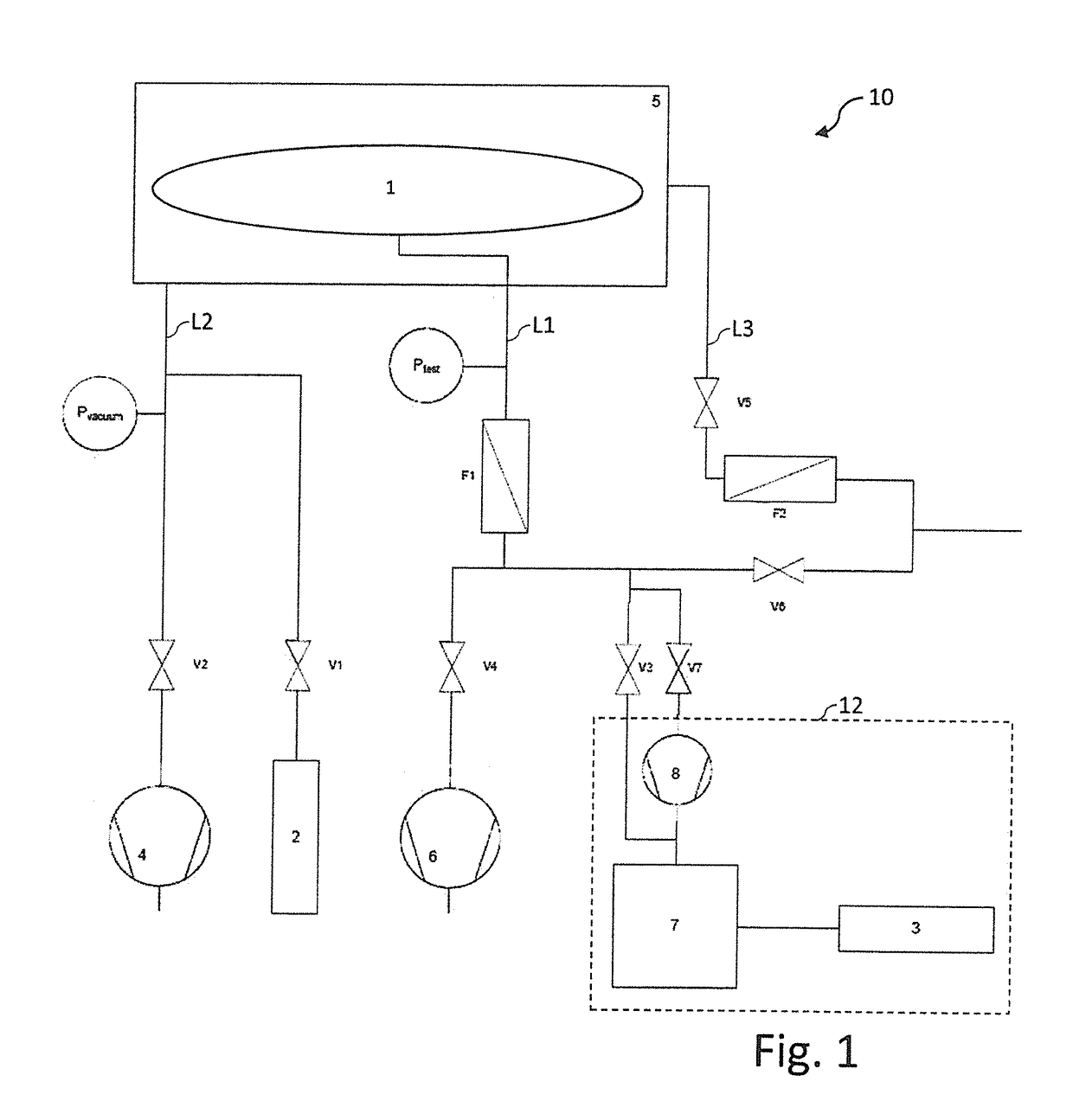
[0059]FIG. 1 shows a schematic representation of an inventive test device 10 according to a preferred embodiment for carrying out an integrity test on a flexible test container 1.
[0060]The test device 10 comprises an inspection container 5, which is preferably designed to be openable and closable in a fluid-tight way. The inspection container 5 may be dimensionally stable and have metal and/or plastic walls, for example. The inspection container 5 is preferably designed and provided to withstand negative pressure, in particular a vacuum, in its interior. “Negative pressure” means that the pressure in the interior of the inspection container is smaller than outside the inspection container. For example, the inspection container 5 may be designed to withstand a pressure in the interior e.g. between about 10−7 mbar and about 100 mbar and an atmospheric pressure of about 1 bar outside the test container, i.e. to remain dimensionally stable and/or fluid-tight substantially at such a pressure difference. An opening of the inspection container 5 (not shown in FIG. 1) may comprise gaskets to ensure a fluid tight seal. The opening may serve to introduce one or more test containers into the inspection container and/or remove it/them and to close the inspection container in a fluid-tight way after the introduction and/or removal of the test container. “Substantially fluid-tight” means that the test container is able keep the pressure difference between the interior and exterior of the inspection container over a sufficiently long time within desired tolerances in order to be able to carry out an integrity test on the bag mounted in the inspection container or the bags mounted in the inspection containers in a reliable way.
[0061]The flexible test container 1 is preferably arranged in a removable way in the inspection container 5. The inspection container 5 may have a mechanical support, in particular a bearing surface matched to the test container 1, on which the test container 1 can be placed in a substantially wrinkle-free manner. The mechanical support may be formed of a porous material, whereby blocking of a leakage of the test container can be prevented by the support.
[0062]The flexible test container 1 to be tested may be formed as a single container or as an assembly of several containers, which are interconnected by hoses, for example. The test container 1 is formed to be at least partially flexible.
[0063]The test container 1 has an opening that is coupled to a test container supply line L1. Via the test container supply line L1, fluids may be supplied to the interior of the test container 1 mounted in the inspection container 5, and/or fluids may be discharged from or pumped out of the interior of the test container 1. In particular, the test container 1 can be evacuated via the test container supply line L1 and/or be filled with test fluid and/or be ventilated.
[0064]For example, during the provision of the negative pressures in the test container 1 and in the inspection container 5, the level of the negative pressure in the test container may be adapted to the level of the negative pressure in the inspection container. Negative pressure in this context means a lower pressure than the pressure outside the inspection container 5, such as atmospheric pressure. Here, for example, both negative pressures can be actively monitored and/or controlled, both negative pressures can be generated via a common vacuum pump and/or a connection valve between the two interior spaces can be opened during the pumping-out process. In particular, in this case maintaining a pressure difference upper limit between the pressure in the interior of the inspection container and the pressure in the interior of the test container may be intended and provided.
[0065]According to a further development of this embodiment, a pressure compensation between the interior of the test container and the interior of the inspection container is carried out during the provision of the negative pressures in the test container and in the inspection container. This can be done e.g. by opening a separating valve between these two interior spaces. Due to the pressure compensation, a harmfully high pressure difference between these two interior spaces is avoided.
[0066]The pressure compensation between the interior of the test container 1 and the interior of the inspection container 5 may be effected by matching between an inspection container pump 4 for pumping or evacuating the interior of the sealed inspection container 5 and a test container pump 6 for pumping or evacuating the interior of the test container 6. Thus, for example one of said at least said two pumps 4 and 6 can be controlled such during operation that the negative pressures in the two interior spaces can be matched to each other. The control of the at least one pump may include throttling, temporarily disabling and/or enhancing the pumping performance.
[0067]Alternatively or in addition, the pressure compensation may be effected by means of a separating valve (not shown). The separating valve is arranged so that it separates the interior of the inspection container 5 from the interior of the test container 1. The separating valve may be arranged in a corresponding connecting line. The separating valve is controllable and can be opened and closed.
[0068]According to one embodiment, a substantially equally high negative pressure is provided in the test container 1 and in the inspection container 5.
[0069]According to the illustrated embodiment, the interior of the inspection container 5 is further preferably connected to two supply lines, namely to an inspection container supply line L2 and to an inspection container vent line L3. Via the inspection container supply line L2 and an inspection container evacuation valve V2, the interior of the inspection container 5 can be connected to an inspection container pump 4. Furthermore, the interior of the inspection container 5 can be connected to an inspection fluid detector 2 via the inspection container supply line L2 and a detector valve V1. The inspection fluid detector 2 suitable for the inspection fluid used serves to detect the inspection fluid exiting the test container 1 in the event of a leak in the test container 1, wherein in the event of a leak at least part of the inspection fluid is present preferably in the interior of the inspection container 5 but outside the test container 1, and can be detected there by the inspection fluid detector 2 from a minimum concentration.
[0070]The inspection fluid detector 2 is designed and provided to detect the concentration of a predetermined inspection fluid in the interior of the inspection container 5. For example, the inspection fluid detector 2 may comprise a gas detector on the basis of a LASER absorption and/or a gas chromatograph and/or a mass spectrometer and/or an optical spectrometer.
[0071]The inspection container pump 4 may be designed as a high vacuum pump that can evacuate the interior of the inspection container 5 preferably to a high vacuum with a pressure of not greater than 10−3 mbar, e.g. to provide a very low background leakage rate in the inspection container 5. Here, the background leakage rate is the detected leakage rate, which is detected if no inspection fluid is introduced into the test container 1 and/or the inspection container 5. The background leakage rate can be influenced for example by inspection fluid still present in the inspection container 5 from previous measurements or by a defective tightness of the inspection container.
[0072]A low background leakage rate enables a fast measurement. The smaller the background leakage rate in the inspection container 5, the more pronounced is a dynamic behavior, such as the increase of the measurement signal, the specific leakage rate. A low background leakage rate thus increases the speed at which a leak or leaking point in the test container 1 can be detected in case of a defect of the test container. 1 Such a dynamic increase in the concentration of inspection fluid in the interior of the inspection container 5, in particular before a significant permeation through side walls of the test container 1 occurs, can be evaluated for the detection of a leak in the test container 1. In particular, the demands on the background leakage rate, namely that the background leakage rate be very low, are particularly important if only a very limited measurement period available due to rapid permeation of the inspection fluid through the test container. In other words, the shorter the duration available for the measurement, the greater the demands on the background leakage rate.
[0073]Arranged in the test container supply line L1 is further a test container filter F1, which is designed as a particle filter and preferably inhibits a passage of particles, in particular dirt particles, through the test container supply line L1.
[0074]Via the test container supply line L1 and a test container pump valve V4, the interior of the test container 1 is connectable to a test container pump 6, which can generate a negative pressure, in particularly vacuum, in the test container 1.
[0075]The test container pump 6 is designed to and provided, simultaneously with the evacuation of the inspection container 5 performed by the inspection container pump 4, to cause the evacuation or pumping of the test container 1, whereby a pressure difference between the interior and the exterior of the test container 1 is reduced or is avoided even completely and thus the risk of damage to the test container 1 due to a strong inflation and/or compression during evacuation can be reduced or eliminated even completely. At the end of the test, the test container pump 6 may be used to evacuate the inspection fluid out of the test container 1, for example.
[0076]Furthermore, the interior of the test container 1 is connected to an inspection fluid supply unit 12 via the test container supply line L1. The inspection fluid supply unit 12 is connected to the test container supply line L1 in parallel via an inspection fluid supply valve V3 and via an inspection fluid discharge valve V7. Here, parallel means that the inspection fluid supply valve V3 and the inspection fluid discharge valve V7 are independently of one another, in particular directly, connected to the test container supply line L1. The inspection fluid supply unit 12 comprises an inspection fluid collection container 7 and an inspection fluid storage container 3. The inspection fluid storage container 3 is connected to the test container supply line L1 via the inspection fluid collection container 7 and is preferably designed to introduce a desired inspection fluid quantity into the inspection fluid collection container 7, if necessary. Between the inspection fluid storage container 3 and the inspection fluid collection container 7 there may be arranged a valve (not shown), so as to control the flow of inspection fluid from the inspection fluid storage container 3 into the inspection fluid collection container 7. Preferably, SF6 is used as the inspection fluid in the embodiment shown.
[0077]The inspection fluid collection container 7 is preferably directly connected to the test container supply line L1 and thus to the test container 1 via the inspection fluid supply valve V3. Further, the inspection fluid collection container 7 is connected to the test container supply line L1 and thus to the test container 1 successively via the inspection fluid discharge valve V7 and via an inspection fluid recycling pump 8.
[0078]The inspection fluid supply unit 2 is designed such that by opening the inspection fluid supply valve V3, inspection fluid can flow from the inspection fluid collection container 7 via the test container supply line L1 into the test container 1. This can preferably take place such that inspection fluid with a test pressure ptest is present in the test container 1, and preferably in the test container supply line L1. The test pressure ptest is preferably in a range from about 1 mbar to about 10 bar, further preferably in a range of from about 10 mbar to about 1 bar, even more preferably in a range from about 20 mbar to about 0.5 bar, most preferably in a range of from about 50 mbar to about 0.35 bar.
[0079]The inspection fluid in the inspection fluid collection container 7 and/or in the inspection fluid storage container 3 may be biased at a predetermined and/or predeterminable test pressure to establish the test pressure in the test container 1 almost immediately by relaxation of the inspection fluid, when the inspection fluid supply valve V3 is opened.
[0080]The inspection fluid supply unit 12 is furthermore designed such that by opening the inspection fluid discharge valve V7, inspection fluid can exit or be pumped out of the test container 1 by the inspection fluid recycling pump 8 via the test container supply line L1, and the pumped inspection fluid can flow into the inspection fluid collection container 7. In particular, the inspection fluid recycling pump 8 can evacuate the test container 1 from the inspection fluid and supply the inspection fluid pumped thereby to the inspection fluid collection container 7 for reuse as part of a further integrity test.
[0081]Preferably, the inspection fluid discharge valve V7 and the inspection fluid supply valve V3 are not opened simultaneously. In other words, preferably the inspection fluid supply valve V3 or the inspection fluid discharge valve V7 or both are closed at any one time.
[0082]In the illustrated embodiment, the test device 10 further comprises an inspection container vent line L3. By opening the inspection container vent valve V5, the inspection container can be vented in particular to atmospheric pressure when required. During ventilation of the inspection container 5, the supply air flows through the inspection container filter F2 to prevent e.g. dirt or debris from entering the inspection container. Furthermore, the test device 10 shown comprises a test container vent valve V6. By opening the test container vent valve V6, the test container 1, in particular the interior of the test container 1, and the associated lines or inspection fluid lines can be ventilated.
[0083]Preferably, the test container pump 6 is arranged outside the inspection container 5, whereby compact dimensioning of the inspection container is made possible.
[0084]The test device 10 may further comprise a controller for controlling the valves and/or pumps of the test device 10. The controller may include a computer processor.
[0085]The test device 10 particularly allows the simultaneous provision of a negative pressure in the inspection container and in the test container.
[0086]In one embodiment, the test device 10 comprises a separating valve between the interior of the test container 1 and the interior of the inspection container 5 (not shown). A pressure compensation can be achieved by means of the separating valve, which reduces a strain on the test container 1 at differently high negative pressures.
[0087]The test device 10 shown in FIG. 1 is used to carry out an integrity test on the flexible test container 1. Here, the test container 1 is interchangeable and not part of the test device 10. Instead, the test device 10 can be used repeatedly for inspecting a plurality of different flexible test containers.
[0088]The sequence of the corresponding test method is shown in a schematic flowchart in FIG. 2. This flowchart indicates individual method steps of a method for carrying out an integrity test on a flexible test container, which are shown in the flowchart of FIG. 2 for controlling the test device 10 shown in FIG. 1.
[0089]The integrity test starts with method step A. At the beginning, all pumps of the test device, in particular the inspection container pump 4 and the test container pump 6, all pumps operate. Preferably, the inspection fluid recycling pump 8 operates as well. Furthermore, at the beginning of the process, all valves of the test device 10 are closed.
[0090]In method step B, both the inspection container 5 and the test container 1 are emptied, more specifically, negative pressure compared to atmospheric pressure is provided in these two containers, for example a high vacuum. This is done by opening the inspection container evacuation valve V2 and the test container pump valve V4, whereby the two pumps 4 and 6 are connected. The evacuation of the test container 1 is preferably carried out simultaneously or parallel to the evacuation of the inspection container 5. For example, to carry out the integrity test, in the inspection container 5 and/or in the inspection fluid detector 2 or in the lines connecting the inspection container 5 with the inspection fluid detector there may be a prevailing pressure in a range of about 10−5 mbar to about 100 mbar, preferably in a range of about 10−3 to about 50 mbar, more preferably in a range from about 0.1 mbar to about 20 mbar.
[0091]In particular, the pressure may be chosen such that the pressure is suitable for the inspection fluid detector 2 used. For this reason, different values of the pressure may be necessary or useful for different types of inspection fluid detectors 2. For example, for an inspection fluid detector 2 based on an optical detection method, such as LASER absorption in particular for the detection of SF6, a pressure of about 10 mbar may be advantageous and/or necessary. In contrast, for a detection of inspection fluid by means of an inspection fluid detector 2 based on a mass spectrometer, a pressure of about 0.1 mbar may be advantageous and/or necessary.
[0092]In method step C, the inspection container evacuation valve V2 and the test container pump valve V4 are closed, so that the respective pumps 4 and 6 are separated from the test container 1 and from the inspection container 5.
[0093]In method step D, the detector valve V1 is opened so that the inspection fluid detector 2 is connected to the inspection container 5. Further, the inspection fluid detector 2 is started or activated or set into operation. Preferably, the collection of measurement data on inspection fluid possibly present in the inspection container 5 starts with the activation of the inspection fluid detector 2. The activation of the inspection fluid detectors 2 can take place before, after, or simultaneously with the opening of the detector valve V1.
[0094]Optionally, after method step D, a check of the starting conditions can be carried out. This may for example be done to achieve a coordinated reaction to different measurement results in the preliminary measurement, i.e. before the start of the main measurement. Under certain circumstances it is possible that the evacuation to the negative pressure in the inspection container 5, in particular to a high vacuum, takes a long time (for example by outgassing from the test container 1). In this case, the background leakage rate in the inspection container 5 can drop sharply. Although this is not negative to the measurement is principle, the dynamic increase of background leakage rate at the start of the main measurement is changed thereby as well. Depending on the method of evaluation, it can therefore be advantageous that the background leakage rate be in a defined window at the start of the main measurement. If this window is exceeded, inspection fluid can be introduced into the inspection container 5 accordingly.
[0095]In method step E, inspection fluid is filled into the test container 1. The test container is mounted in the inspection container 5 for carrying out the integrity test. Filling of the inspection fluid into the test container 1 takes place by opening the inspection fluid supply valve V3. Here, inspection fluid is filled into the test container 1 until a test pressure ptest is reached in the test container 1. Preferably, the test pressure ptest is such that the test container 1 inflates, i.e. substantially unfolds, and the test container 1 is filled substantially absolutely. “Substantially absolutely” in this context means that due to the inspection fluid located therein at test pressure ptest, the test container 1 or the shell material at least partially tightens without mechanical stresses occurring, which damage the test container 1 or the shell material of the test container 1 or adversely affect it otherwise. Preferably, after filling of the test container 1, the inspection fluid supply valve V3 is closed again.
[0096]Thus, with method step E, the actual main measurement of the integrity test begins. In method step E, the test container 1 is evaluated. After a predetermined and/or predeterminable test time TestTime has lapsed without the signal provided by the inspection fluid detector 2 exceeding a predetermined limit RejectLimit from the start of the measurement until the end of the test time TestTime, the test container 1 is judged to be tight (method step F2). If the predetermined limit RejectLimit is exceeded, i.e. if the inspection fluid detector 2 detects a larger amount of inspection fluid or a greater change rate of inspection fluid in the inspection container 5 than a predetermined limit RejectLimit, the test container 1 is judged to be not tight or defective (method step F1). Here, the process can be terminated already before the end of the test time TestTime to avoid an increased contamination of the inspection container 5 with inspection fluid.
[0097]In method step G, the inspection fluid detector 2 is disconnected from the inspection container 5 and the main measurement is stopped. The inspection fluid detector 2 is disconnected by closing the detector valve V3, which terminates the measurement. Preferably, the inspection fluid detector 2 is stopped or its operation is stopped.
[0098]In method step H, the inspection fluid present in the test container 1 test fluid is pumped out of the test container 1. This is done by the inspection fluid supply unit 12, in particular by the inspection fluid recycling pump 8 by opening the inspection fluid discharge valve V7. The inspection fluid pumped out of the test container 1 is supplied to the inspection fluid collection container 7 by the inspection fluid recycling pump 8 and is available there preferably for further integrity tests. Pumping of the test fluid out of the test container 1 is considered completed when the predominant pressure in the test container 1 is not greater than a value Limit1_ptest. The value Limit1_ptest is preferably not greater than 10 mbar, more preferably not more than 1 mbar, particularly preferably not greater than 10−2 mbar, most preferably not greater than 10−4 mbar.
[0099]In particular, it may be advisable to recycle the inspection fluid when the procurement of the inspection fluid is associated with a significant financial effort and/or if adverse effects of inspection fluid escaping into the atmosphere could adversely affect the environment and/or people nearby. If there is no risk of such restrictions, omission of the recycling of inspection fluid may be a more efficient solution in some cases.
[0100]In method step I, the test device 10 is vented. If a predetermined pressure in the test container 1 if fallen below due to the recycling process and if the inspection fluid is thus essentially completely evacuated from the test container 1, the valve V7 is closed again. Thereafter, the test device 10 is vented, i.e. in particular the test container 1, the inspection container 5, as well as at least partially the associated lines. Ventilation may be accomplished by opening the valves V5 and V6. Preferably, ventilation takes place until atmospheric pressure is reached in the vented parts of the test device 10.
[0101]In method step J, the end of the integrity test has been reached. After reaching the atmospheric pressure in the vented parts of the test device 10, the valves V5 and V6 are closed and the test device 10 is thus brought to the starting position, so that a new test procedure can be started.
[0102]Optionally, the interior of the test containers is flushed after inspection fluid has been detected in the inspection container 5. If a test object, i.e. a test container 1, is defective, inspection fluid will enter the interior of the inspection container 5 from the test container 1 during the test procedure. To avoid damage to the inspection container 5 by contamination with the inspection fluid, it will be cleaned by flushing after a test container 1 has been tested to be defective. After testing of an integer test container, flushing is not necessarily required and can be omitted. Thus, the interior of the inspection container 5 may be flushed in particular only after each test in which a test container 1 was rated defective. This is a further advantage of the method according to the invention, since due to the low permeation of inspection fluid through integer shell material, the quantity of inspection fluid getting into the inspection container is much smaller than in case of use of an inspection fluid having a higher permeation rate.
[0103]Further, a background concentration of inspection fluid is optionally set in the inspection container 5. Under certain circumstances, providing the negative pressure in the inspection container can take a long time, particularly in the event of outgassing from the test container. In this case, the background leakage rate may drop sharply as well. Although this is basically rather positive for the implementation of the integrity test, the dynamic increase of the leakage rate can be changed at the beginning of the measurement. Depending on the evaluation method of the integrity test, it may therefore be advantageous that the background leakage rate be in a predefined range and/or window at the beginning of the measurement. If this predefined range is fallen below, e.g. inspection fluid can be introduced into the inspection container. Thus, the background concentration of inspection fluid in the inspection container is set actively before starting the measurement for verifying the integrity of the test container.
[0104]FIG. 3A is a diagram showing several curves L0 to L3 of time courses of the measured leakage rate of inspection fluid at which the inspection fluid enters the inspection container 5 from the test container 1, and is measured by the inspection fluid detector 2. For the integrity tests, their time course of the leakage rate being shown in FIG. 3, gaseous He was used as the inspection fluid. Each of the tested, identical test containers was a bag comprising a layer of the EVOH plastic material, wherein the shell material has a total thickness or a wall thickness of 360 μm and the bag has a capacity of 50 l. The permeation of inspection fluid through intact shell material is essentially determined by said layer of EVOH. The pressure difference between the interior of the bag and the immediate exterior of the bag was 50 mbar.
[0105]A first time course L0 shows the time course of the leakage rate of helium as an inspection fluid of an undamaged test container, i.e. a bag that does not have any leak. Although the test container 1 of the measurement L0 has no leak, the measured leakage rate increases significantly already after approximately 5 seconds. The inspection fluid stream from the test container 1 into the inspection container 5 underlying this increase of this leakage rate is caused by permeation of the inspection fluid through the shell material, in particular through undamaged shell material.
[0106]A second time course L1 shows the time course of the leakage rate of helium of a test container with a leak of 2 μm in diameter. A third time course L2 shows the time course of the leakage rate of helium inspection fluid of a test container with a leak of 5 μm in diameter. A fourth time course L3 shows the time course of the leakage rate of helium as the inspection fluid of a test container with a leak of 7 μm in diameter. The leaks were created by forming a hole with the precisely defined diameters in the shell material of the test container by means of a LASER. In all curves in FIG. 3, a background leakage rate between about 1.5·10−7 and 2.10−7 mbar·l/s at the time t=0 can be identified.
[0107]The time courses L1, L2, and L3 of the leakage rates of the bags having a leak show a more rapid increase of the leakage rate over time than the intact bag without leak of the curve L0. Independent of the leak size, the curves L1, L2 and L3 have very similar thresholds or saturation values, which the respective time courses approach asymptotically (see FIG. 3B). The increase of the corresponding leakage rates is caused by an inspection fluid stream through the respective leak in the shell material on the one hand, and also by a permeation of helium through the intact shell material on the other hand, as can be seen from the intact bag in curve L0. In particular in the case of longer test times, with this inspection fluid stream the differently sized leaks can no longer be determined in a reliable manner due to the increasing contribution by the permeation. For this reason, only a very short time period of a few seconds, such as between 4 and 8 seconds after filling the bags, is available for an integrity test of such bags. Between 0 and 4 seconds after filling, there is the risk of the measurement result being influenced by the system inertia, as the inspection fluid may possibly not have flown in completely. Starting at a time of about 10 seconds after filling, however, the inspection fluid stream occurring due to permeation complicates the distinction of bags with differently sized leaks and tight bags.
[0108]The reason that the leakage rate increases particularly at the beginning with time and is not constant over time is particularly the inertia of the test system 10. Despite all the optimizations of the test procedure, in particular the inspection fluid needs time to flow into the test container and spread therein. Especially in large test containers 1, such as in bags with a large capacity of several liters or even several 10 or 100 liters, the inertia of the system is expressed in the measurement curves. For this reason, a reliable determination of leaks can be done only after a period of several seconds as a rule. Furthermore, it is also advisable to consider only those measurement values that were only collected when the system had enough time for a significant signal increase, i.e. when enough helium exited through the leak and reached the inspection fluid detector 2. In the curves shown, this is the case after about 4 seconds.
[0109]Since, already after a few seconds, the measured leakage rate change due to permeation increases more sharply than the leakage rate change due to a leak having a diameter of a few μm, the detectability of leaks having a diameter of a few μm decreases drastically already after a few seconds due to the permeation of He. As shown in FIG. 3, it is almost impossible to distinguish the curves L0 to L3 and the time courses of the leakage rates in the case shown already after 14 seconds. Thus, a reliable detection of leaks can be carried out only up to about 10 seconds after filling of the test container with helium.
[0110]Thus, with helium as the inspection fluid, the reliable performance of the integrity test is only possible in a short period of a few seconds, namely between about 4 and about 10 seconds after filling of the test container 1 in the cases shown in FIG. 3A. While the lower time limit is given by the reaction time of the test system 10 or the inspection fluid, the upper limit time is determined by the period in which the permeation of inspection fluid through the shell material of the test container 1 has not yet reached the level of the leakage rates of the smallest leaks to be detected. In particular in the case of integrity tests of test containers 1 or bags with a large capacity, this often leads to problems, since they require a long reaction time of the test system 10 and on the other hand thus also have a large surface of shell material and a high level of permeation.
[0111]FIG. 3B shows the same measured leakage rates of FIG. 3A on a longer time scale, which ranges from 0 to 120 seconds. To avoid repetitions, contents that have already been explained with reference to FIG. 3A will not be discussed in more detail here. In FIG. 3B, it can be seen in particular that all curves, i.e. L0, L1, L2 and L3, approach very similar saturation values or end values of the leakage rate. This does therefore not allow a reliable distinction among leaking bags with various leak sizes and/or the detection of leaking bags, since the contribution of substantially the same permeation rate of all bag has the largest contribution to the signals measured as the leakage rates.
[0112]In particular, it can be seen in FIG. 3B that for the tested bags, which have a capacity of about 50 l and a shell material area of about 8106 cm2 and were tested with He as the inspection fluid at a pressure difference of about 50 mbar, the He leakage rate of the tight bag (curve L0) has a value of about 5·10−4 mbar·l/s. This corresponds to a permeation rate of about 1.2·10−5 mbar·m/(s·bar) determined taking the shell material surface of the bag and the pressure difference into account. A reliable integrity test of such bags, especially bags of such a size, is thus hardly possible with He.
[0113]By analogy with FIG. 3A, FIG. 4 also shows a diagram with multiple curves L0 to L3 of time courses of the leakage rates of inspection fluid at which the test fluid enters the inspection container 5 from the test container 1, and is measured by the inspection fluid detector 2. For the time courses shown in FIG. 4, however, no gaseous He as in FIG. 3A was used, but SF6 (sulfur hexafluoride) according to another embodiment. The tested test containers 1 were identical to the corresponding test containers 1 of FIGS. 3A and 3B. To avoid repetitions, only the differences with respect to the diagram shown in FIG. 3A will be discussed.
[0114]In contrast to the curve L0 in FIG. 3A, the curve L0 in FIG. 4 remains substantially at a constant value of about 1.5.10-7 mbar·l/s, which corresponds to the background leakage rate. “Substantially at a constant value” means that there is no perceivable change and in particular no change that has a significant impact on the integrity test. The value of the background leakage rate further indicates that the permeation rate of SF6 of the tested bags does not exceed a value of 3.7·10−7 mbar·l/(s·bar), since otherwise the determined leakage rate for a tight bag (curve L0) would exceed the constant measured background leakage rate.
[0115]Accordingly, in combination with the test containers 1 or bags or shell materials of the test containers 1 to be tested as part of the invention, there is no appreciable permeation of SF6 through the shell material when SF6 is used as the inspection fluid. The reason for this may be that the permeation of SF6 through the shell material of the test container 1 is significantly less than the permeation of He. This may be because SF6 consists of comparatively large molecules and He of comparatively small atoms. Other gases comprising molecules or atoms with comparatively large dimensions in at least one direction in space (compared to He) can therefore often have a low permeation through the shell material of the test container.
[0116]Since the permeation substantially does not make a contribution to the measured leakage rate in the curves L1, L2 and L3 in FIG. 4, the measured leakage rates L1, L2 and L3 differ more strongly among each other than the corresponding leakage rates in FIG. 3. This allows an easier and more reliable determination of the leak size based on the measured leakage rate.
[0117]Furthermore, the period during which the test container 1 retains the inspection fluid efficiently and/or the permeation does not take on disturbing proportions with respect to the measurement is considerably longer than the corresponding period for the use of He in FIG. 3. This has the advantage that the performance of the integrity test, or measurement of the leakage rate, can be started at a later time after filling of the test container 1 and/or can be carried out over a longer period after filling of the test container 1 without having to fear a negative influence on the measurement by permeation of inspection fluid. This is particularly advantageous for testing large test containers 1 that have a large surface area and/or require a longer period to achieve a steady state after filling of the test container 1. In other words, the use of SF6 in the illustrated embodiment reduces disturbing influences on the measurement result due to permeation, as occurs with the use of He as the inspection fluid, and allows a later start and/or a temporal extension of the measurement time in a integrity test, which is particularly advantageous for integrity tests on large-volume test containers 1, such as bags with a capacity of more than 10 l.
[0118]FIG. 5 shows a diagram that plots a calculated equivalent size of leaks against the volume or the capacity of the test container 1 to be tested by a conventional He-based integrity tests. In other words, the diagram in FIG. 5 shows how large the diameter of an equivalent leak in the test container of a specific volume or capacity is so that it causes an inspection fluid stream that is equal to the inspection fluid stream due to permeation through the shell material of the test container. By means of a permeation study, in which the permeation of He through a film comprising an EVOH layer was assessed, the permeation rate of He was determined and then the corresponding values for the respective sizes of the surface of the bag with the corresponding volumes were determined. During the permeation study, a pressure difference of 1 bar was set on both sides of the EVOH layer.
[0119]It can be seen that for a 50 l bag, for example the permeation causes or allows an inspection fluid stream corresponding to the inspection fluid stream through a leak of about 30 μm in diameter. In an integrity test of such large bags, when using He as the inspection fluid, a detection of leaks with a diameter smaller than 30 μm would not or hardly be possible. Instead, a reliably detectable hole would have to have a much larger diameter than 30 μm, which therefore severely limits the suitability of a conventional integrity test in particular on the basis of He for assessing the integrity of such large bags.
[0120]If, nevertheless, a conventional method for an integrity test, in particular using He as the inspection fluid, of large-volume bags is used, only a very limited period of a few seconds is available to assess the tightness of the bag before the contribution of the permeation complicates the interpretation of the measurement signal or makes it impossible. Especially for bags with large volumes, however, unfolding or inflation of the bag may take a few seconds, so that too short a measurement time can distort the measurement result as well (see FIG. 3). Thus, a conventional method for performing integrity tests on such large bags can only be used to a very limited extent and has significant drawbacks in terms of a minimum size of detectable leaks.
[0121]This disadvantage can be overcome with the use of the inventive method for carrying out an integrity test, since such a small permeation rate, such as of SF6, causes a much smaller inspection fluid stream and thus disturbing influences of the permeation on the measurement signal are much less pronounced than in conventional methods, or are even completely eliminated (see FIG. 4). Thus, the method according to the invention is particularly suitable and efficient for the performance of integrity tests for bags having a volume of several liters.
[0122]Furthermore, the invention relates to the following aspects:
[0123]A method 1 for performing an integrity test on a flexible test container, wherein [0124] the test container is arranged in an inspection container that can be closed in a fluid-tight manner, [0125] negative pressure is provided in the interior of the closed inspection container, [0126] an inspection fluid is filled into the test container arranged in the inspection container, [0127] inspection fluid present in the interior of the inspection container is detected, and [0128] negative pressure is provided prior to filling the inspection fluid into the test container arranged in the inspection container.
[0129]A method 2 according to method 1, wherein the negative pressure is provided in the test container before and/or while the negative pressure is provided in the interior of the inspection container.
[0130]A method according to methods 1 or 2, wherein during provision of the negative pressures in the test container and in the inspection container, the level of the vacuum in the test container is adjusted to the level of the vacuum in the inspection container.
[0131]A method according to method 4, wherein during provision of the negative pressures in the test container and in the inspection container, a pressure compensation between the interior of the test container and the interior of the inspection container takes place.
[0132]A method according to method 5, wherein the pressure compensation between the interior of the test container and the interior of the inspection container takes place by [0133] a coordination between an inspection container pump for evacuating the interior of the closed inspection container and a test container pump for evacuating the interior of the test container and/or [0134] by means of a separating valve.
[0135]A method 6 according to one of the preceding methods, wherein the vacuum in the test container is provided via a supply line via which the inspection fluid is filled into the test container as well.
[0136]A method 7 according to one of the preceding methods, wherein the interior of the inspection container is flushed after inspection fluid has been detected in the inspection container.
[0137]A method 8 according to one of the preceding methods, wherein a background concentration of inspection fluid is set in the inspection container.
[0138]A test device 1 for carrying out an integrity test on a flexible test container, with [0139] an inspection container that can be closed in a fluid-tight manner, in which the test container can be arranged, [0140] an inspection container pump for evacuating the interior of the closed inspection container, [0141] an inspection fluid source from which an inspection fluid can be filled into the test container arranged in the inspection container, [0142] an inspection fluid detector for detecting inspection fluid in the interior of the inspection container, and [0143] a pumping connection via which the interior of the test container arranged in the inspection container can be evacuated.
[0144]A test device 2 according to the test device 1, with a separating valve between the interior of the test container and the interior of the inspection container.
[0145]A use of the test device according to the test devices 1 or 2 for carrying out an integrity test on a flexible test container according to the method of one of the methods 1 to 8.
LIST OF REFERENCE NUMERALS
[0146] 1 test container [0147] 2 inspection fluid detector [0148] 3 inspection fluid storage container [0149] 4 inspection container pump [0150] 5 inspection container [0151] 6 test container pump [0152] 7 inspection fluid collection container [0153] 8 inspection fluid recycling pump [0154] 10 test device [0155] 12 inspection fluid supply unit [0156] L1 test container supply line [0157] L2 inspection container supply line [0158] L3 inspection container vent line [0159] F1 test container filter [0160] F2 inspection container filter [0161] V1 detector valve [0162] V2 inspection container evacuation valve [0163] V3 inspection fluid supply valve [0164] V4 test container pump valve [0165] V5 inspection container vent valve [0166] V6 test container vent valve [0167] V7 inspection fluid discharge valve [0168] ptest test pressure [0169] TestTime test time [0170] RejectLimit limit (tightness of the test container)
Login to view more PUM


Description & Claims & Application Information
We can also present the details of the Description, Claims and Application information to help users get a comprehensive understanding of the technical details of the patent, such as background art, summary of invention, brief description of drawings, description of embodiments, and other original content. On the other hand, users can also determine the specific scope of protection of the technology through the list of claims; as well as understand the changes in the life cycle of the technology with the presentation of the patent timeline. Login to view more.
Login to view more Similar technology patents
Active co neutralizing device
InactiveUS20120014839A1Prevent poisoningMore timeFlow control using electric meansAlarmsChemistryCarbon monoxide poisoning
Owner:PEN TU CHENG
Method of detecting the relative positioning of two signals and corresponding device
ActiveUS20060056557A1Limit riskMore timeMultiple input and output pulse circuitsSynchronisation information channelsEngineeringClock signal
Owner:STMICROELECTRONICS SRL
Structural health monitoring sensor
ActiveUS20200363304A1More timeCheapForce measurementMaterial strength using tensile/compressive forcesTension stressStrain gauge
Owner:ANDERSON DOUGLAS
Use of edible-oil-processing spent bleaching earth in formulating poultry and livestock feed products
ActiveUS20180042268A1More timeSpontaneous combustion be eliminateFood processingAnimal feeding stuffLivestockChemistry
Owner:SMALLWOOD NORMAN J
Emergency brake assist system for a vehicle
InactiveUS20180186350A1More timeAutomatic initiationsExternal condition input parametersAutomotive engineeringEmergency brake assist
Owner:CONTI TEMIC MICROELECTRONIC GMBH
Classification and recommendation of technical efficacy words
- More time
- Reliable method
Multiple path reactive routing in a mobile ad hoc network
ActiveUS6961310B2Less traffic load concentrationMore timeFrequency-division multiplex detailsData switching by path configurationTelecommunications linkRanking
Owner:STINGRAY IP SOLUTIONS LLC
Passive ranging techniques in borehole surveying
ActiveUS6937023B2More timeReduce riskElectric/magnetic detection for well-loggingSurveyMeasurement deviceSurveyor
Owner:SCHLUMBERGER TECH CORP
System and Method for Collecting Evidence Pertaining to Relationships Between Biomolecules and Diseases
InactiveUS20080195570A1Increase efficiencyMore timeBiostatisticsChaos modelsSubject specificOrganism
Owner:KONINKLIJKE PHILIPS ELECTRONICS NV
Method and apparatus for teaching how to execute a predetermined motion
InactiveUS20060094523A1More timeGymnastic exercisingGolfing accessoriesPostural orientationAnimation
Owner:HALL CAROLYN WALLIS
Compositions and methods for separation of moieties on chips
InactiveUS6858439B1Reliable methodMore separatedSequential/parallel process reactionsElectrostatic separatorsChemistryMicroparticle
Owner:AVIVA BIOSCI
Methods and apparatus for enhancing the robustness of watermark extraction from digital host content
InactiveUS20060239502A1Reliable methodLow costUser identity/authority verificationSpeech analysisTelecommunicationsComputer science
Owner:IP ACQUISITIONS LLC
Methods and Systems for Validating Code from a Wireless Device
InactiveUS20110018692A1Reliable methodReadily apparentError preventionSensing detailsIntegrated circuitAloha
Owner:ENSURGE MICROPOWER ASA
Aerodynamic Measurement Probe of an Airstream Along a Wall
ActiveUS20100186497A1Simple and reliableReliable methodVolume measurement and fluid deliveryIndication/recording movementPhysicsAirflow
Owner:THALES SA
Capacitive acceleration sensor arrangement
ActiveUS20060162454A1Simple principleReliable methodCapacitance measurementsAcceleration measurementMeasurement deviceClassical mechanics
Owner:MURATA MFG CO LTD