This helps you quickly interpret patents by identifying the three key elements:
Problems solved by technology
Method used
Benefits of technology
Benefits of technology
The invention is a short optical imaging lens that has good and stable image quality. It has a concave and convex shape design that allows for a larger field of view and larger aperture stop while keeping the lens system short. The lens is easy to design and process, and provides good optical performance and image quality.
Problems solved by technology
However, a minimized optical imaging lens that has good image quality cannot be made by purely scaling down a lens that has good image quality; the design process involves material characteristics, and actual problems on the aspect of production, such as manufacturing and assembling yields must be considered.
Method used
Image
Click on the blue label to locate the original text in one second.
Reading with bidirectional positioning of images and text.
Examples
first embodiment
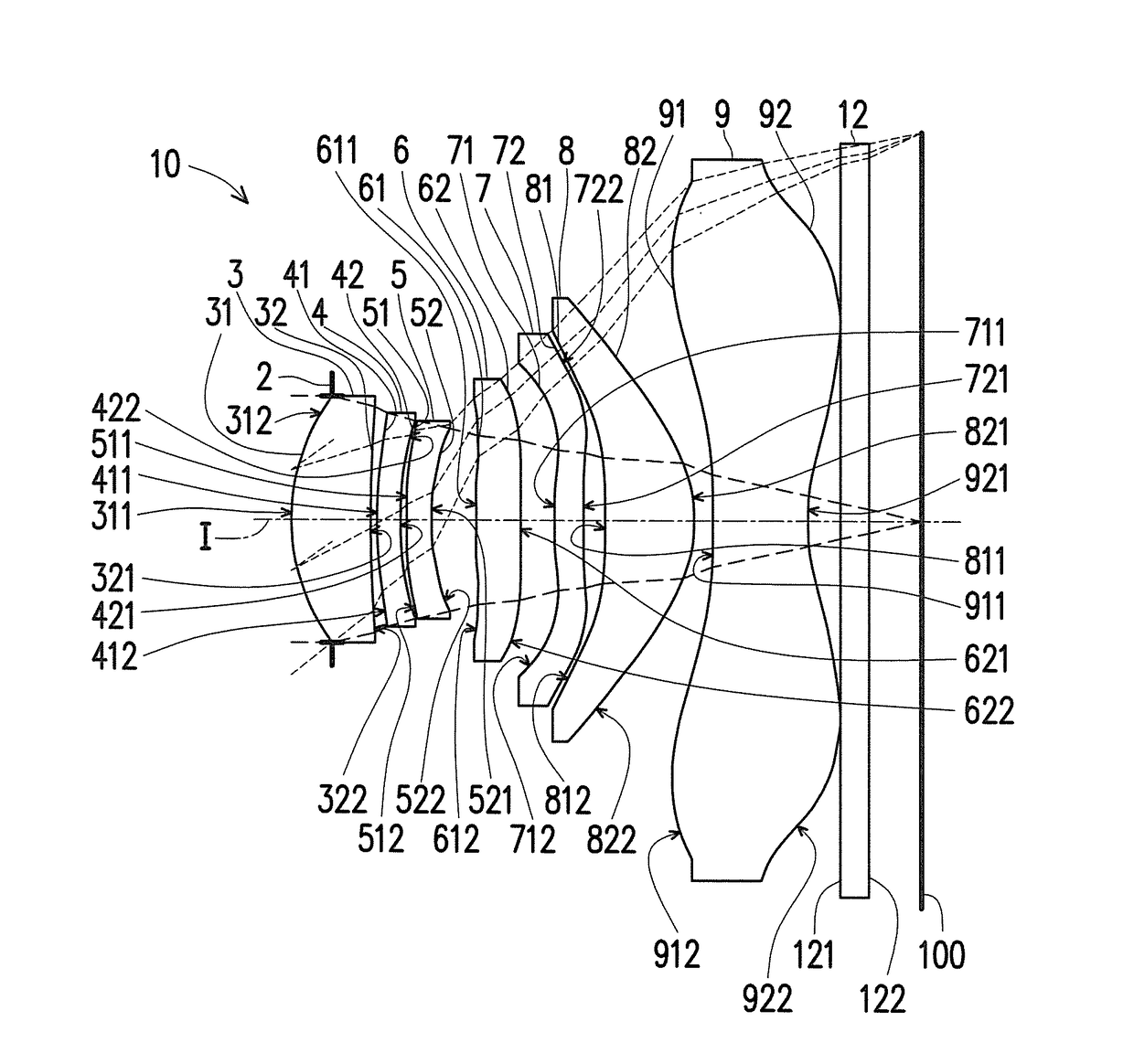
[0090]In addition, the relations among important parameters pertaining to the optical imaging lens 10 in the first embodiment are shown in FIGS. 50 and 51.
[0091]Wherein,
[0092]EFL represents an effective focal length of the optical imaging lens 10;
[0093]T1 represents a thickness of the first lens element 3 along the optical axis I;
[0094]T2 represents a thickness of the second lens element 4 along the optical axis I;
[0095]T3 represents a thickness of the third lens element 5 along the optical axis I;
[0096]T4 represents a thickness of the fourth lens element 6 along the optical axis I;
[0097]T5 represents a thickness of the fifth lens element 7 along the optical axis I;
[0098]T6 represents a thickness of the sixth lens element 8 along the optical axis I;
[0099]T7 represents a thickness of the seventh lens element 9 along the optical axis I;
[0100]G12 represents an air gap from the first lens element 3 to the second lens element 4 along the optical axis I (namely, the distance from the imag...
second embodiment
[0139]The detailed optical data pertaining to the optical imaging lens 10 is shown in FIG. 12, and the effective focal length of the total system in the second embodiment is 4.329 mm, the HFOV thereof is 37.497°, Fno thereof is 2.000, the system length thereof is 5.501 mm, and the image height is 3.32 mm.
[0140]FIG. 13 shows the aspheric coefficients used in the formula (1) of the object-side surface 31 of the first lens element 3 through the image-side surface 92 of the seventh lens element 9 in the second embodiment.
[0141]In addition, the relations among important parameters pertaining to the optical imaging lens 10 in the second embodiment are shown in FIGS. 50 and 51.
[0142]The longitudinal spherical aberration of the second embodiment shown in FIG. 11A is simulated in the condition that the pupilradius is 1.0650 mm. According to the longitudinal spherical aberration diagram of the second embodiment shown in FIG. 11A, a deviation of the imaging points of the off-axis rays of diff...
third embodiment
[0145]The detailed optical data pertaining to the optical imaging lens 10 is shown in FIG. 16, and the effective focal length of the total system in the third embodiment is 4.260 mm, the HFOV thereof is 37.098°, the Fno thereof is 1.994, the system length thereof is 5.383 mm, and the image height is 3.33 mm.
[0146]FIG. 17 shows the aspheric coefficients used in the formula (1) of the object-side surface 31 of the first lens element 3 through the image-side surface 92 of the seventh lens element 9 in the third embodiment.
[0147]In addition, the relations among important parameters pertaining to the optical imaging lens 10 in the third embodiment are shown in FIGS. 50 and 51.
[0148]The longitudinal spherical aberration of the third embodiment shown in FIG. 15A is simulated in the condition that the pupilradius is 1.0650 mm. According to the longitudinal spherical aberration diagram of the third embodiment shown in FIG. 15A, a deviation of the imaging points of the off-axis rays of diffe...
PUM
Abstract
An optical imaging lens includes a first lens element, a second lens element, a third lens element, a fourth lens element, a fifth lens element, a sixth lens element and a seventh lens element arranged in order from an object side to an image side along an optical axis. Each lens element has an object-side surface and an image-side surface. The first lens element has positive refracting power, and the image-side surface of the first lens element has a concave portion in a vicinity of a periphery. The third lens element has negative refracting power, and the image-side surface of the third lens element has a concave portion in a vicinity of a periphery. At least one of the object-side surface and the image-side surface of the fourth lens element is aspheric surface, and at least one of the object-side surface and the image-side surface of the fifth lens element is aspheric surface. The sixth lens element has positive refracting power, and the image-side surface of the seventh lens element has a concave portion in a vicinity of the optical axis.
Description
CROSS-REFERENCE TO RELATED APPLICATION[0001]This application claims the priority benefit of China application serial no. 201611253471.9, filed on Dec. 30, 2016. The entirety of the above-mentioned patent application is hereby incorporated by reference herein and made a part of this specification.BACKGROUND OF THE INVENTION1. Field of the Invention[0002]The present invention relates to an optical lens, and in particular, to an optical imaging lens.2. Description of Related Art[0003]In recent years, as use of portable electronic devices (e.g., mobile phones and digital cameras) becomes ubiquitous, techniques related to producing image modules have also been developed significantly, wherein the image module mainly includes an optical imaging lens, a module holder unit and a sensor, and the demand for minimized image module increases due to the compact and slim design of mobile phones and digital cameras. Moreover, as dimensions of a charged coupled device (CCD) and complementary metal-...
Claims
Application Information
Patent Timeline
Application Date:The date an application was filed.
Publication Date:The date a patent or application was officially published.
First Publication Date:The earliest publication date of a patent with the same application number.
Issue Date:Publication date of the patent grant document.
PCT Entry Date:The Entry date of PCT National Phase.
Estimated Expiry Date:The statutory expiry date of a patent right according to the Patent Law, and it is the longest term of protection that the patent right can achieve without the termination of the patent right due to other reasons(Term extension factor has been taken into account ).
Invalid Date:Actual expiry date is based on effective date or publication date of legal transaction data of invalid patent.

