
Dual depth exit pupil expander

Active Publication Date: 2018-07-05
MAGIC LEAP
View PDF19 Cites 51 Cited by
  • Summary
  • Abstract
  • Description
  • Claims
  • Application Information

AI Technical Summary

Benefits of technology

The patent describes an eyepiece for a head-mounted display that uses a waveguide to guide light from a location closer to the edges of the eyepiece. The eyepiece has at least one out-coupling optical element that receives the light guided in the waveguide and out-couples it to a first and second region of the eyepiece. The optical element has optical power to output the light from the eyepiece with a first and second depth of origin. The eyepiece can also include an in-coupling optical element that directs more light of a first wavelength into the waveguide than a second wavelength. The eyepiece can be used in a head-mounted display to provide a realistic view of the virtual or augmented reality.

Problems solved by technology

Because the human visual perception system is complex, it is challenging to produce an AR technology that facilitates a comfortable, natural-feeling, rich presentation of virtual image elements amongst other virtual or real-world imagery elements.

Method used


Image

  • Dual depth exit pupil expander
  • Dual depth exit pupil expander
  • Dual depth exit pupil expander

Examples


Embodiment Construction

[0130]Reference will now be made to the figures, in which like reference numerals refer to like parts throughout. It will be appreciated that embodiments disclosed herein include optical systems, including display systems, generally. In some embodiments, the display systems are wearable, which may advantageously provide a more immersive VR or AR experience. For example, displays containing one or more waveguides (e.g., a stack of waveguides) may be configured to be worn positioned in front of the eyes of a user, or viewer. In some embodiments, two stacks of waveguides, one for each eye of a viewer, may be utilized to provide different images to each eye.

Example Display Systems

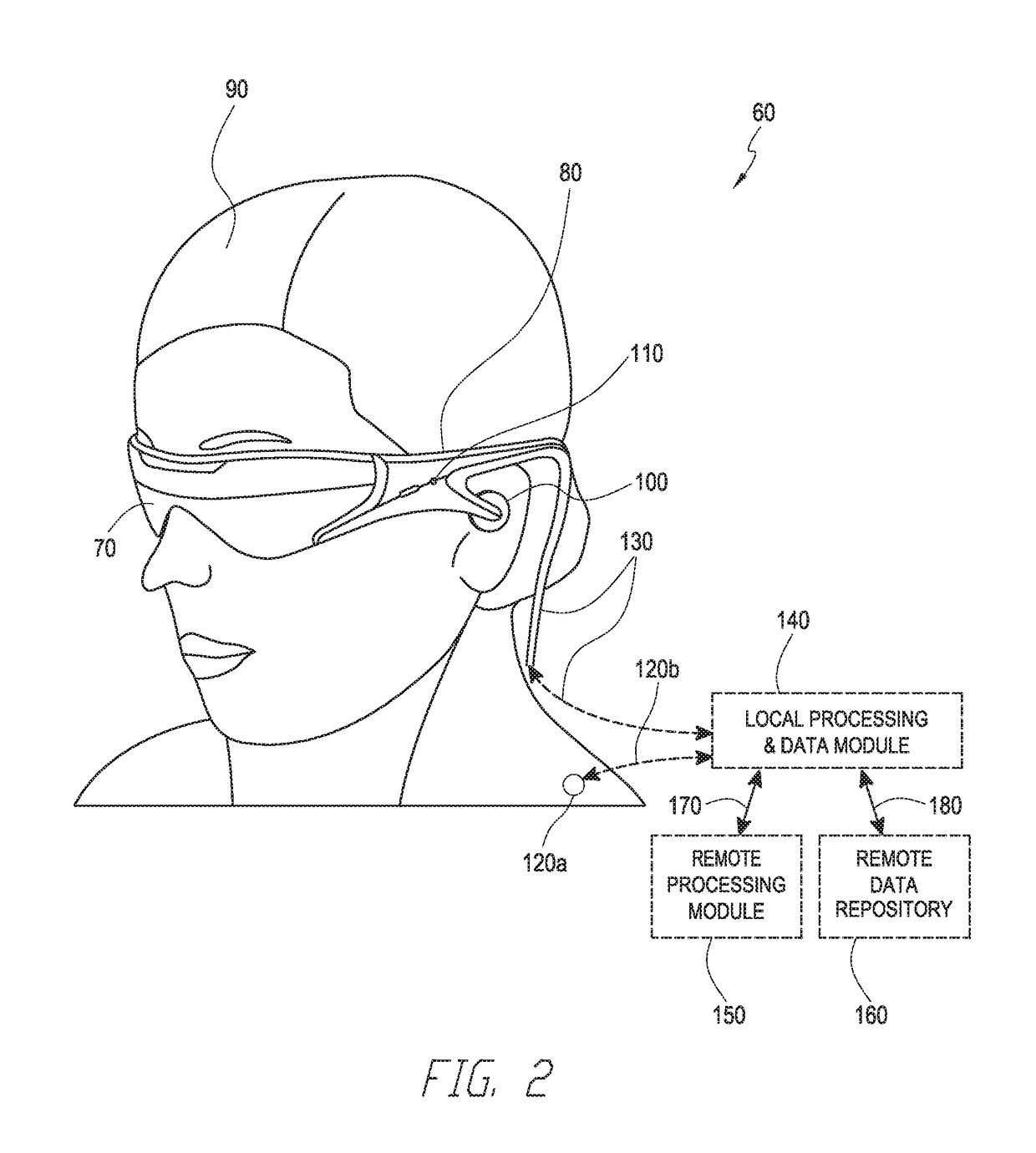
[0131]FIG. 2 illustrates an example of wearable display system 60. The display system 60 includes a display 70, and various mechanical and electronic modules and systems to support the functioning of that display 70. The display 70 may be coupled to a frame 80, which is wearable by a display system user or view...


PUM


Abstract

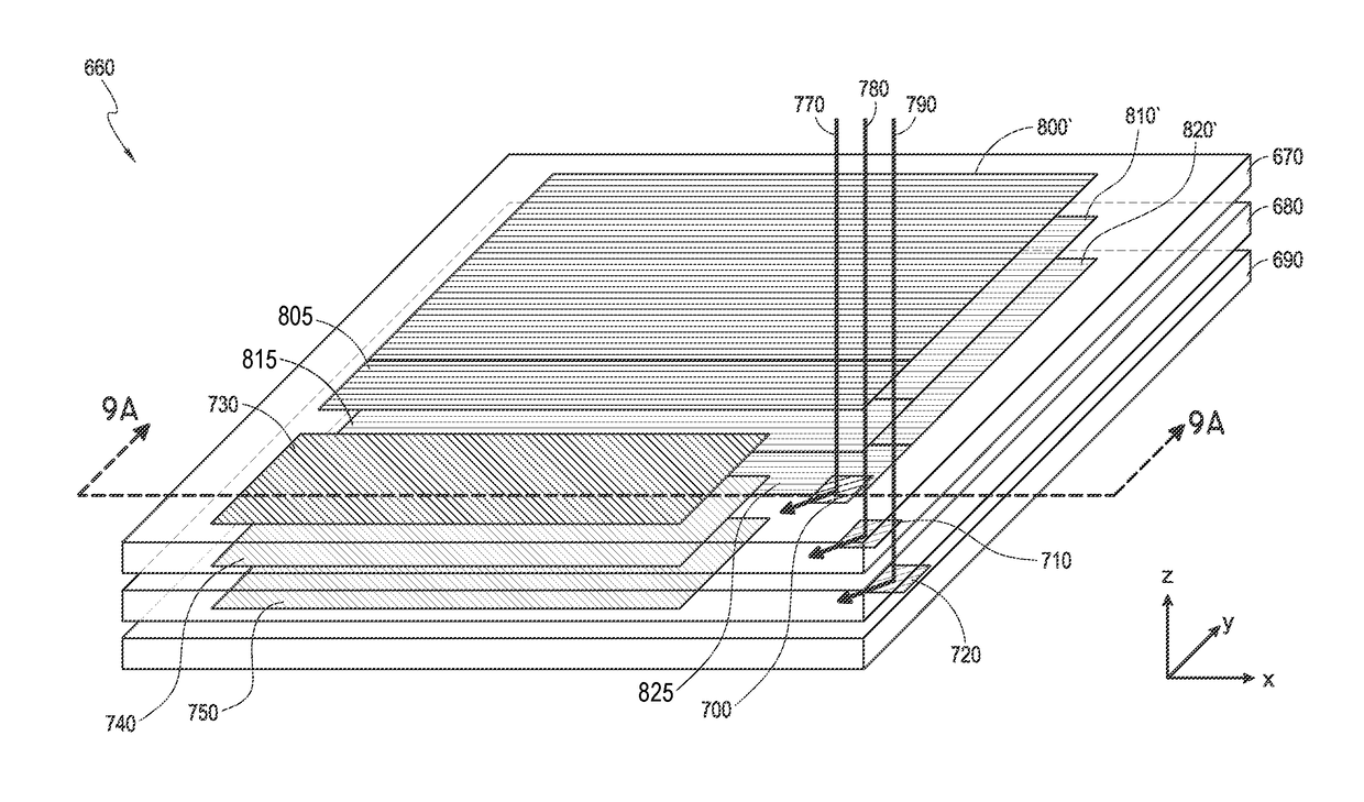
An optical device includes a waveguide including an in-coupling optical element configured to in-couple light into the waveguide, a light distributing element configured to receive light from the in-coupling optical element and distribute light at a selected wavelength, and an out-coupling optical element configured to receive light from the light distributing element and out-couple light out of the waveguide. The out-coupling optical element includes a first region configured to out-couple light at a first depth plane based on a lens function of the first region and a second region configured to out-couple light at a second depth plane based on a different lens function of the second region.

Description

INCORPORATION BY REFERENCE[0001]This application claims priority under 35 U.S.C. § 113339(e) from U.S. Provisional Application No. 62 / 439,848, filed Dec. 28, 2016, entitled “DUAL DEPTH EXIT PUPIL EXPANDER,” which is hereby incorporated by reference herein in its entirety and for all purposes. This application additionally incorporates by reference the entirety of each of the following patent applications: U.S. application Ser. No. 14 / 555,585 filed on Nov. 27, 2014; U.S. application Ser. No. 14 / 690,401 filed on Apr. 18, 2015; U.S. application Ser. No. 14 / 212,961 filed on Mar. 14, 2014; U.S. application Ser. No. 14 / 331,218 filed on Jul. 14, 2014; and U.S. application Ser. No. 15 / 072,290 filed on Mar. 16, 2016.BACKGROUNDField[0002]The present disclosure relates to optical devices, including virtual reality and augmented reality imaging and visualization systems.Description of the Related Art[0003]Modern computing and display technologies have facilitated the development of systems for ...

Claims


Application Information

Patent Timeline
IPC IPC(8): G02B27/00G02B27/01G02B3/00G02B3/04F21V8/00
CPCG02B27/0081G02B27/0172G02B3/0062G02B3/04G02B6/0026G02B6/003G02B2027/0123G02B2027/0174G02B27/0179G02B27/017G02B2027/0185
Inventor BROWY, ERIC C.SOMMERS, JEFFREY SCOTT
Owner MAGIC LEAP
Learn More