Method for counting and characterization of particles in a fluid in movement
Active Publication Date: 2018-07-05
COMMISSARIAT A LENERGIE ATOMIQUE ET AUX ENERGIES ALTERNATIVES
View PDF3 Cites 6 Cited by
Summary
Abstract
Description
Claims
Application Information
AI Technical Summary
This helps you quickly interpret patents by identifying the three key elements:
Problems solved by technology
Method used
Benefits of technology
Problems solved by technology
However, holograms do not allow cells to be reliably counted wh
Method used
Image
Click on the blue label to locate the original text in one second.
Reading with bidirectional positioning of images and text.
Examples
Example
[0100]Various embodiments are envisionable. According to a first embodiment, the image sensor acquires two successive images I(t1) and I(t2) at the first time t1 and at the second time t2, respectively. From each image, three-dimensional coordinates of particles at each time are obtained. According to a second embodiment, one and the same image of the fluidic chamber is acquired at two times, this image being acquired at the first time and the second time.
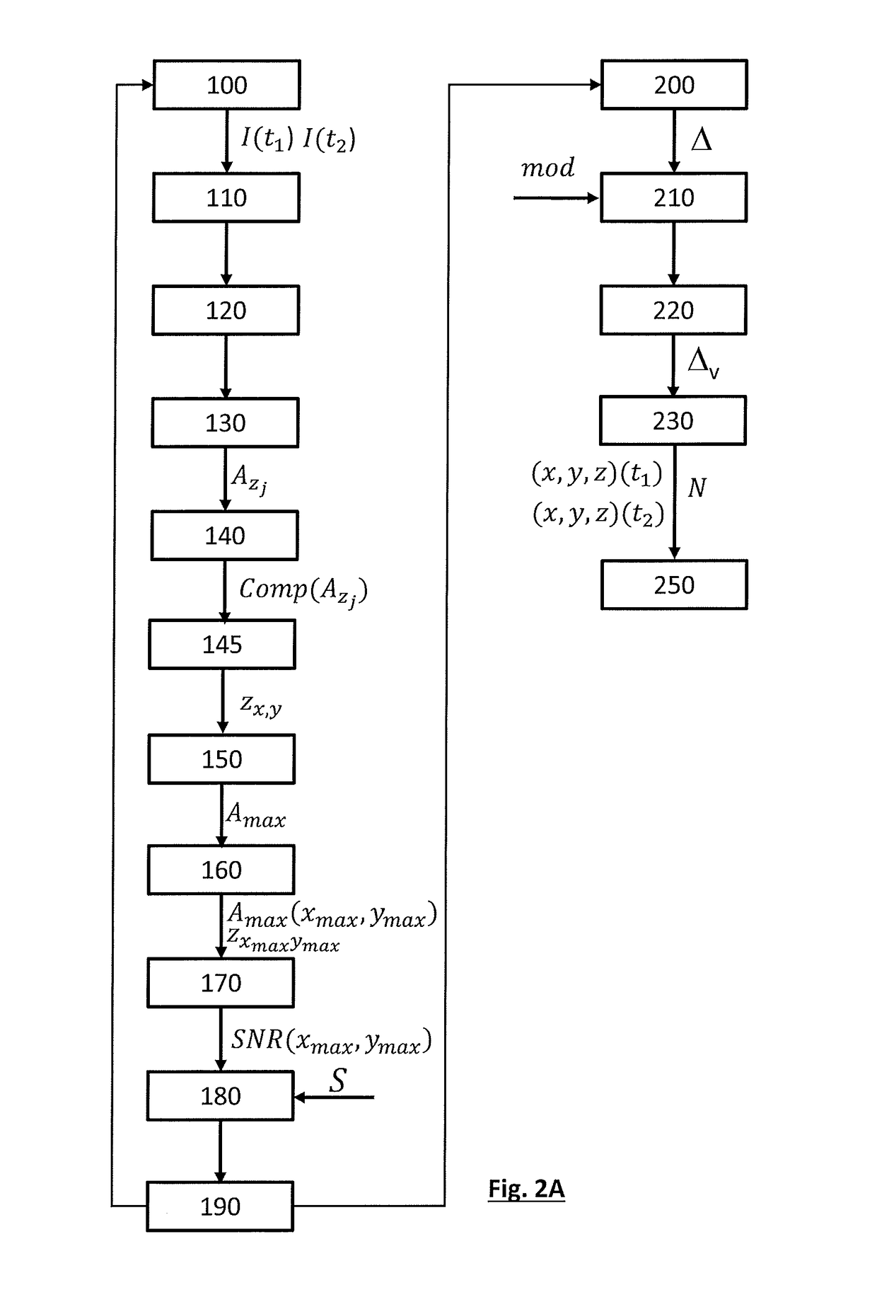
[0101]The main steps of the first embodiment of the method are described below, with reference to FIG. 2A.
[0102]Step 100: acquisition. It is a question of acquiring an image I(ti) at various times ti at an acquisition frequency. In a first iteration, the time ti is a first time t1 and an image called the first image I(t1) is acquired. In a second iteration, the time ti is a second time t2, the second time being subsequent to the first time. The image acquired at the time t2 is a second image I(t2).
[0103]Step 110: an image of intere...
Example
[0155]According to a second embodiment, the sample is illuminated with two pulses at a first time t1 and at a second time t2, respectively, and an image I the exposure time of which comprises the first time and the second time is acquired. Thus, in one and the same image, a signal representative of the positions of the particles at the first and second times is obtained. The steps of this embodiment are shown in FIG. 4A and described below:
[0156]Step 300: successively illuminating the sample at the first time and at the second time, and acquiring an image I, called the first image, through the first time and through the second time. The time interval between the two times may be very short, for example 5 ms.
[0157]Step 320: frequency filtering, analogously to step 120.
[0158]Step 330: propagating the filtered image, analogously to step 130, in order to obtain a stack of complex images.
[0159]Step 340: extracting a component of each complex image of the stack of complex images.
[0160]Ste...
PUM
Abstract
The invention is a method allowing particles to be tracked in a moving fluid, via an optical method. The particles are in motion in a fluidic chamber. An image of the fluidic chamber is acquired, so as to obtain three-dimensional positions of particles in the fluidic chamber at a first time. Three-dimensional positions of particles at a second time are also obtained, the second time being subsequent to the first time. On the basis of the obtained three-dimensional positions, potential movements of particles, between said times, are established. On the basis of a model of movement of the particles, potential movements are validated. The validated movements allow the particles in the fluid to be counted. In addition, if the particles are of different nature, the movement model may comprise a component of movement of the particles with respect to the fluid that is characteristic of this difference. Determining this component then allows the particles to be characterized.
Description
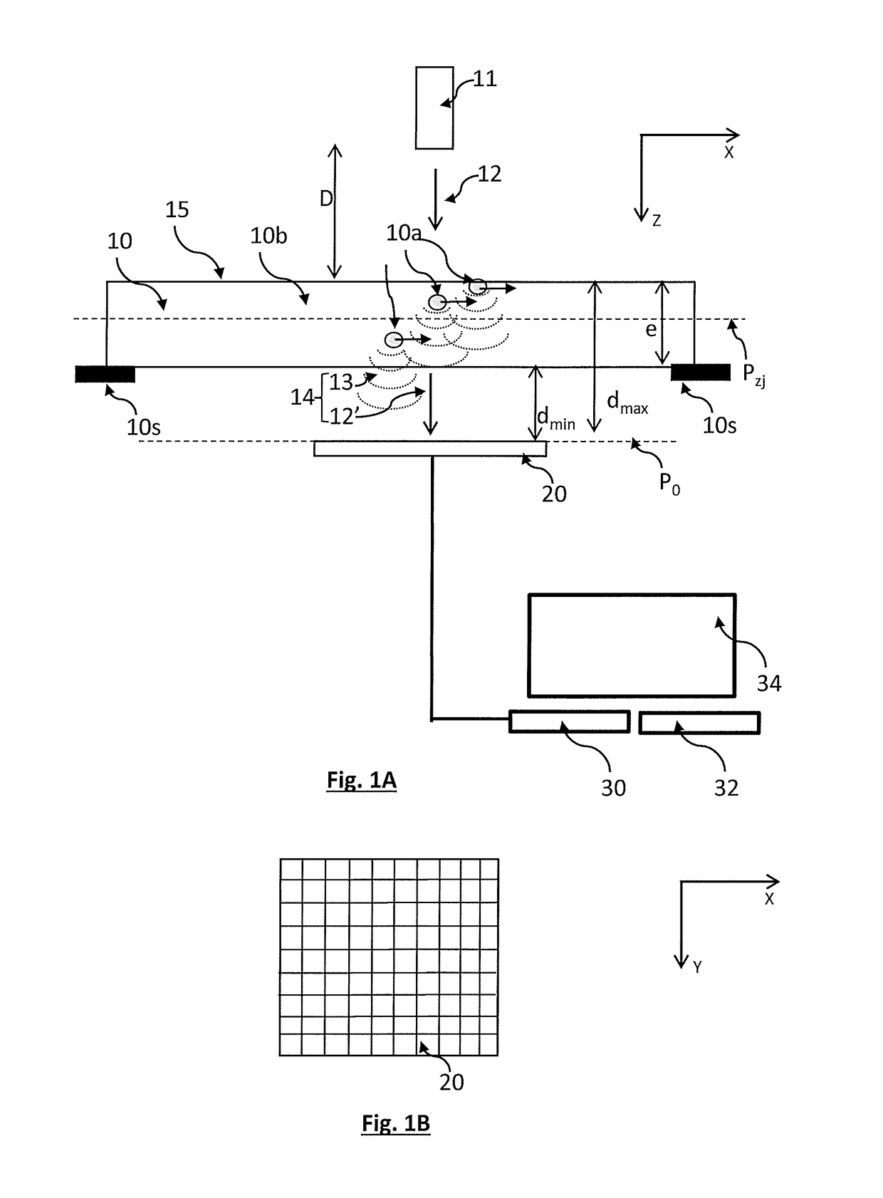
TECHNICAL FIELD[0001]The technical field of the invention is the counting of particles flowing through a fluidic chamber using an optical method.PRIOR ART[0002]Several optical methods have already been employed to count particles circulating in a fluid, the fluid being a gas or a liquid. A very widespread technique is based on the illumination, using a light beam, of a fluid in which particles are flowing. When a particle passes through the beam, some of the light is scattered and may be detected by a photodetector. This technique has been employed to detect particles in air, or to detect cells in liquids, biological liquids for example.[0003]Other methods are based on the analysis of images, for example using a microscope, but such images provide only two-dimensional information as regards the position of the particles.[0004]Document WO2008090330 describes a device allowing samples including cells to be observed via lensless imaging. The sample is placed between a light source and ...
Claims
Application Information
Patent Timeline
Application Date:The date an application was filed.
Publication Date:The date a patent or application was officially published.
First Publication Date:The earliest publication date of a patent with the same application number.
Issue Date:Publication date of the patent grant document.
PCT Entry Date:The Entry date of PCT National Phase.
Estimated Expiry Date:The statutory expiry date of a patent right according to the Patent Law, and it is the longest term of protection that the patent right can achieve without the termination of the patent right due to other reasons(Term extension factor has been taken into account ).
Invalid Date:Actual expiry date is based on effective date or publication date of legal transaction data of invalid patent.

