

Integrally woven or knitted textile with pouch and methods of making the same
- Summary
- Abstract
- Description
- Claims
- Application Information
AI Technical Summary
Benefits of technology
Problems solved by technology
Method used
Image

Examples
first embodiment
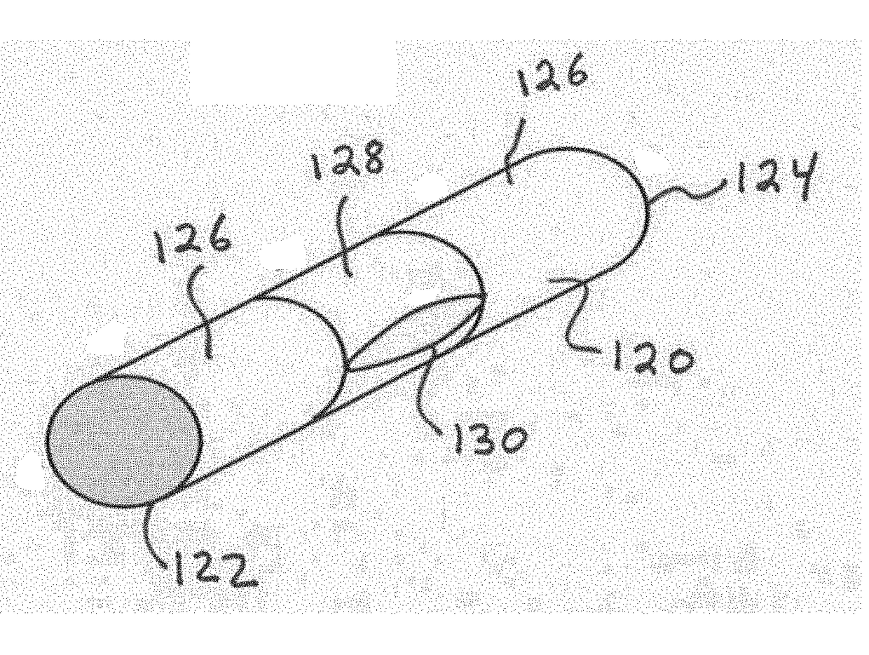
[0033]When the textile is a tubular graft, the pouch may also be tubular and at least partially, substantially or completely circumscribes the underlying tubular graft. For example, the pouch may be donut-shaped about the underlying tubular graft. According to an embodiment, an element, such as a radiopaque marker (e.g., a wire), may be disposed or threaded through one slit opening in a pouch. By eliminating the step of having to sew the element into the graft, fabrication time and the associated cost are reduced. In addition, due to the seamless, integral formation of the pouch and graft, there is no puncturing of the polymeric graft material, and no seams. A “seam” is a line along which two pieces of material are joined together. In contrast, to make the graft of the present disclosure, the longitudinal tubular graft portion and pouch about the graft are joined by interweaving or interknitting whereby at least a portion of a set of yarns are shared between them; in other words, th...
second embodiment
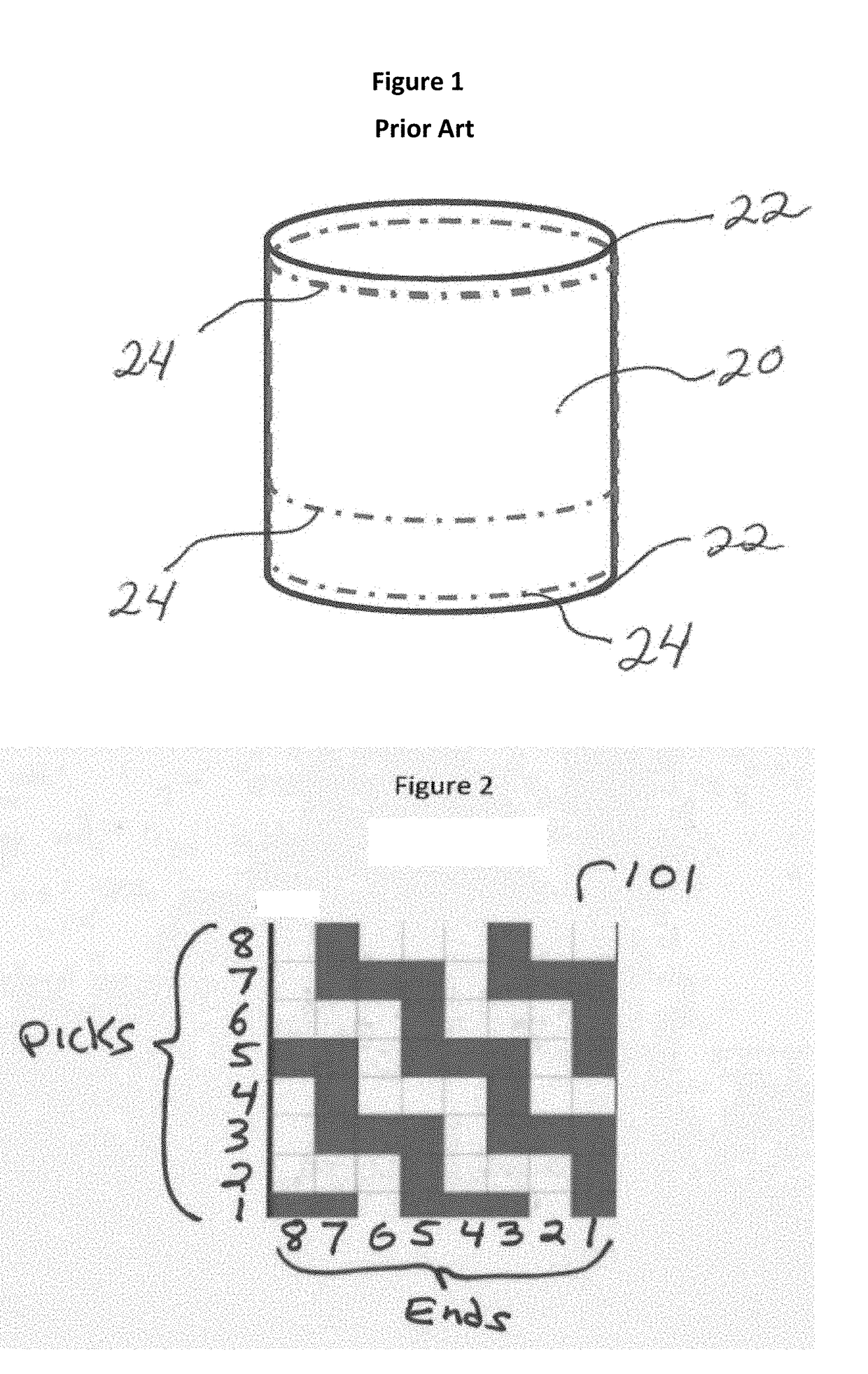
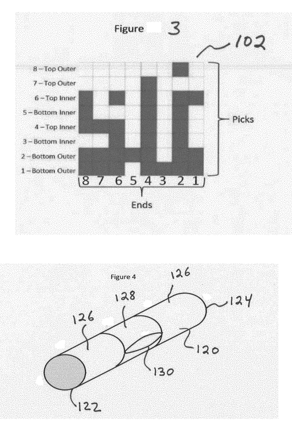
[0054]A second embodiment relates to an integrally woven graft having a first end, a second end and a length therebetween. The integrally woven graft comprises a longitudinal tubular graft portion woven from a set of yarns, and at least one tab or pouch woven from at least a portion of the same set of yarns and integrally woven with the longitudinal tubular graft portion. As such, the graft is made up of multiple segments. The graft may be of any known shape or design, including but not limited to, a straight longitudinal graft, a tapered graft, a flared graft, a stepped graft, a bifurcated or multifurcated graft, a fenestrated graft, or a combination of these shapes and configurations, e.g. a bifurcated graft having tapered and / or stepped portions. Similarly, the multiple segments of a graft may also vary in shape and construction within a single product. The graft may include one longitudinal tubular graft portion or, in other embodiments, multiple segments of longitudinal tubular...
third embodiment
[0097]A third embodiment relates to an integrally knitted textile having a first end, a second end and a length therebetween. The integrally knitted textile comprises a longitudinal textile portion knitted from a set of yarns, and at least one tab or pouch knitted from at least a portion of the same set of yarns and integrally knitted with the longitudinal textile portion. As such, the textile is made up of multiple segments. The textile may include one longitudinal textile portion or, in other embodiments, multiple segments of textile portions that may be joined by one or more integrally knitted pouches knitted there between. In one embodiment, the textile or tape may be knitted in the construction of single layer or double layer material. The textile may be constructed with two or more layers knitted together for a thicker or thinner and denser or less dense textile. In another embodiment, the process to knit a textile with integral pouches utilizes a single guide bar for the fabr...
PUM
| Property | Measurement | Unit |
|---|---|---|
| Angle | aaaaa | aaaaa |
| Length | aaaaa | aaaaa |
| Bioabsorbable | aaaaa | aaaaa |
Abstract
Description
Claims
Application Information