Graft-Catheter Vascular Access System

a vascular access system and catheter technology, applied in the field of medical devices, can solve the problems of skin injury, inconvenience for patients, and devices that have experienced, and achieve the effects of avoiding venous anastomosis, preventing thrombosis, and reducing the risk of infection

Inactive Publication Date: 2013-04-25
CR BARD INC
View PDF10 Cites 14 Cited by
  • Summary
  • Abstract
  • Description
  • Claims
  • Application Information

AI Technical Summary

Benefits of technology

[0011]In accordance with the teachings of the present invention, a graft-catheter is provided. The graft-catheter provides an improved method of vascular access by eliminating many of the complications of prior art devices. The graft-catheter can be implanted subcutaneously thereby eliminating skin level infections. The device connects an

Problems solved by technology

Often the devices are permanently inserted into the patient, but such devices have experienced a variety of problems.
This design is plagued by infection and clotting problems at the sites where the tubing passes through the skin surface.
External shunts further pose an inconvenience to the patient because of the extra care that is required to avoid snagging the exposed tubing which could result in injury to the skin and to dislodging the device.
However, such a fistula may not be used for several weeks after formation because significant time is required for the walls of the dilated vein to thicken sufficiently.
In addition, the required, repeated needle punctures eventually weaken and destroy the arterialized vein, which, to begin with, is subject to abnormal pressurization and is particularly susceptible to collapse.
The ePTFE bridge graft creates a loop between an artery and a vein, by suturing one end of the graft to an artery and the other end to a vein, but this device is prone to complications such as thrombosis, infection, and infiltration of scar-forming cells.
After sufficient healing, surrounding body tissues grow into the walls of the

Method used


Image

  • Graft-Catheter Vascular Access System
  • Graft-Catheter Vascular Access System
  • Graft-Catheter Vascular Access System

Examples


first embodiment

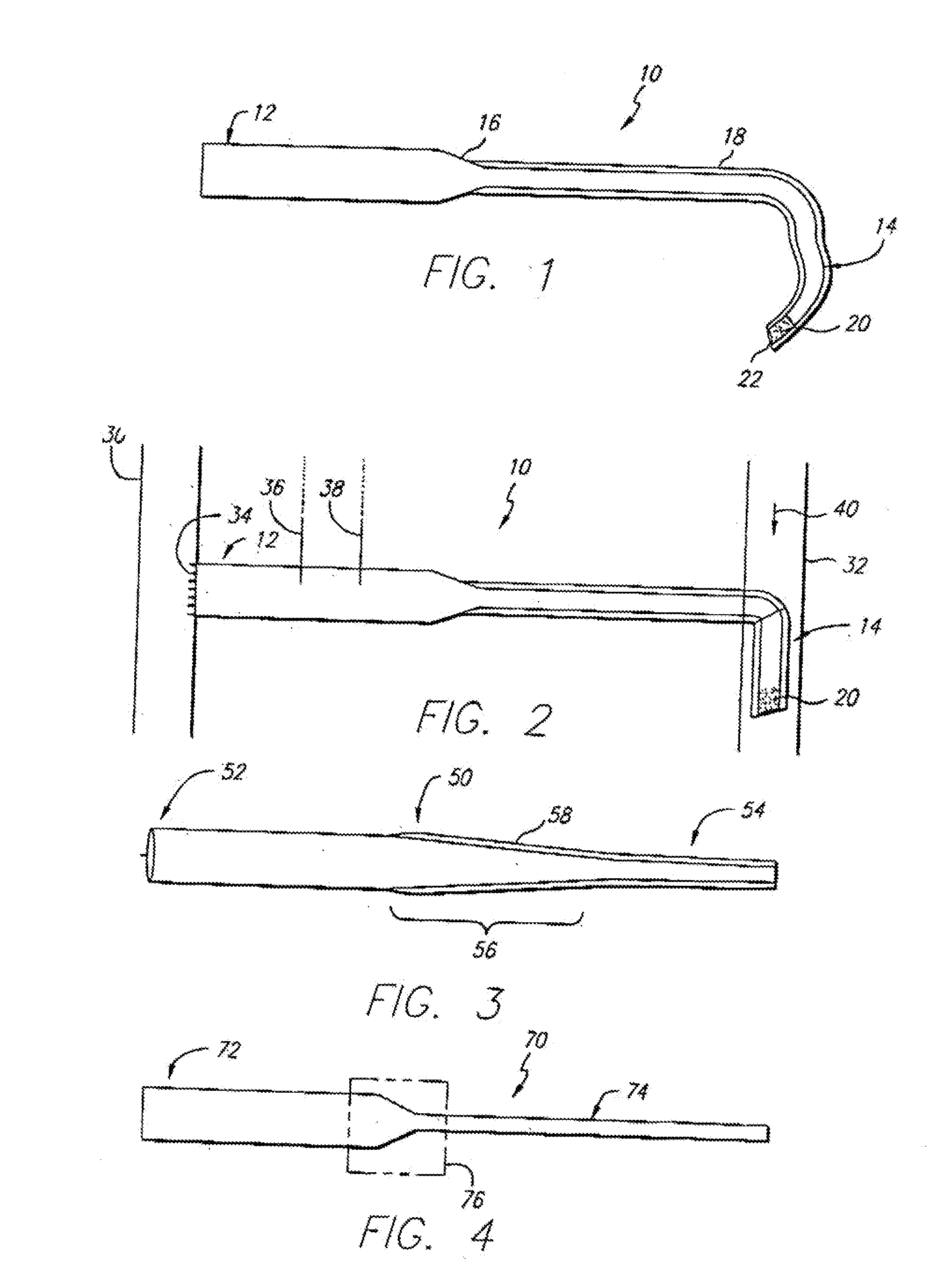
[0035]Referring first to FIG. 1, a side sectional view of a graft-catheter 10 in accordance with the present invention is illustrated. The graft-catheter 10 has a graft section 12 and a catheter section 14 that is long and flexible. The graft section 12 transitions to the catheter section 14 at a tapered region 16. The diameter of the graft section 12 and the catheter section 14 will vary depending upon the size of the patient and the corresponding artery and vein selected. As an example, the diameter of the graft section 12 may be 5-8 millimeters (mm), the tapered region 16 will taper in diameter over a short segment of the graft-catheter 10, and the diameter of the catheter section 14 may be 2-5 mm. The catheter section 14 may have a plurality of transverse holes 20 for optimal blood dispersion and a beveled end 22 for ease of insertion into a vein (not shown). The beveled end 22 and the plurality of transverse holes 20 allow blood to flow optimally through each and into the vein....

second embodiment

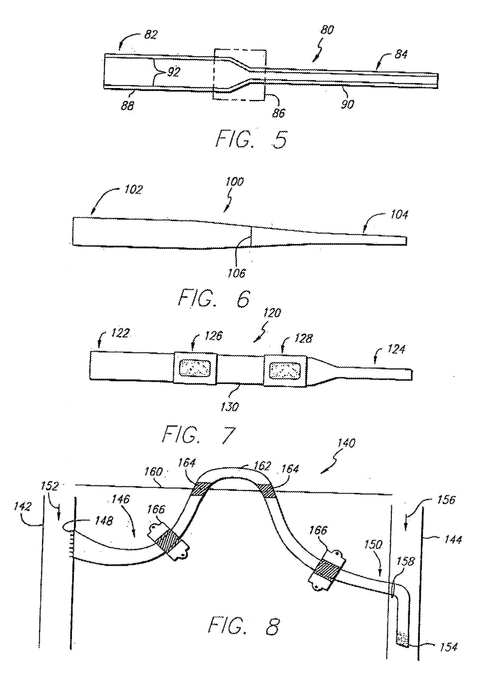
[0039]FIG. 3 shows a side sectional view of a graft-catheter 50 in accordance with the present invention. The graft-catheter 50, similar to the graft-catheter 10, has a graft section 52 and a catheter section 54, but a tapered region 56 tapers in a much more gradual fashion than the tapered region 16 of the graft-catheter 10. The more gradual transition from the graft section 52 to the catheter section 54 provides superior blood flow and improvements in the blood flow mechanics as the blood transitions through the graft-catheter 50 from an artery to a vein. As discussed above, the graft-catheter 50 may be comprised of ePTFE with a polyurethane coating 58 over the catheter section 54 (as shown) or, alternatively, the polyurethane coating 58 may completely coat the graft-catheter 50. Furthermore, the graft-catheter 50 may include an inner polyurethane coating (not shown) as discussed in further detail for certain of the following embodiments.

third embodiment

[0040]FIG. 4 illustrates a side sectional view of a graft-catheter 70 in accordance with the present invention. The graft-catheter 70 has a graft section 72 and a catheter section 74. The graft section 72 may be comprised of ePTFE and the catheter section 74 may be comprised of polyurethane. The graft section 72 may be joined to the catheter section 74 in region 76 by an injection molded hub process, as known in the art. This eliminates having to coat the catheter section with polyurethane, as discussed above, but the graft section 72 may, if desired, be coated with polyurethane to provide stiffness and aid in sealing puncture sites. As an alternative to the injection molded hub process, the graft section 72 may be adhesive bonded or sutured to the catheter section 74 either prior to insertion in the patient or during a surgical procedure to insert the graft-catheter 70 or to replace one of its sections.

[0041]FIG. 5 illustrates a side sectional view of a graft-catheter 80 in accorda...


PUM


Abstract

A vascular access device, for implantation at least partially below the skin of a patient to provide an arteriovenous fistula, includes a graft portion coupled to a catheter portion. The graft portion is sutured to an opening in an artery while the catheter portion is inserted into a vein so that its end lies within the vein downstream from the point of entry into the vein. The device may be comprised of ePTFE with an outer polyurethane coating or the graft portion may comprise ePTFE with an outer polyurethane coating and the catheter portion may comprise polyurethane. There may also be an inner polyurethane coating. Alternatively, the device may be comprised entirely of polyurethane.

Description

PRIORITY[0001]This application is a division of U.S. patent application Ser. No. 09 / 333,637, filed Jun. 15, 1999, which is incorporated by reference in its entirety into this application.BACKGROUND OF THE INVENTION[0002]1. Field of the Invention[0003]The present invention relates to medical devices, and more particularly, to a device that provides an improved method for vascular access.[0004]2. Description of Related Art[0005]Providing frequent, direct, vascular access has become a necessity for many medical procedures including hemodialysis, chemotherapy, various tests requiring frequent blood draws and treatments requiring frequent intravenous administration of drugs. Many vascular access devices have been developed to meet this need. Often the devices are permanently inserted into the patient, but such devices have experienced a variety of problems. For example, the arteriovenous shunt includes a length of silicone rubber tubing bearing catheter tips at each end that are respecti...

Claims


Application Information

Patent Timeline
IPC IPC(8): A61M39/10A61B17/00A61B17/11A61F2/06A61L29/00A61L31/04A61L31/06A61L31/10A61M1/14A61M1/36A61M25/00A61M25/18
CPCA61B17/11A61M39/10A61B2017/1135A61F2/064A61L31/048A61L31/06A61L31/10A61M1/3655A61B2017/1107C08L27/18C08L75/04
Inventor DIFIORE, ATTILIO E.
Owner CR BARD INC
Why Eureka
Try Eureka