
Method of monitoring and assessing the operation of an industrial installation driven by a programmable controller and equipment implementing said method

a programmable controller and industrial installation technology, applied in the direction of electric programme control, program control, instruments, etc., to achieve the effect of accelerating corrective actions and being easy to understand by users

Active Publication Date: 2018-07-19
TLOGIC AUTOMATION
View PDF13 Cites 4 Cited by
  • Summary
  • Abstract
  • Description
  • Claims
  • Application Information

AI Technical Summary

Benefits of technology

The present invention offers an ergonomic solution to track the changes of various variables in real-time, such as boolean, numerical, and complex variables, in a user program and "addon" instances modules. This allows the controller's behavior to be easily viewed and interpreted by the user in a graphic form, without using additional resources. The "graphic form" visualizes only state changes of each variable, their exact values, and the time-stamp of these changes. The user can use this information to make informed decisions and take corrective actions, either outside or during production. The invention can be used with any type of controller, regardless of the manufacturer. Additionally, the invention allows the user to inhibit monitoring of certain variables to reduce metadata volume and increase recording time.

Problems solved by technology

So, the writing of a user program is complex and unique.
Therefore, developing a user program is tedious, delicate and consequently costly.
This is mainly due to the realization constraints of the user programs and to the operational difficulties of the programs and / or of the installations, which can be very frequent and difficultly identifiable, as well during the test phase as during the commissioning phase of the programmable controller on the production site.
These requests from external systems are called asynchronous as they can occur at any time during the execution of the user program, unlike synchronous requests, which would then be processed at a specific location and time in the user program and which would therefore be less efficient than an asynchronous request for the mentioned need.
These exchanges, which are complementary to the usual tasks of the controller, increase its workload and therefore affect its reactivity in answering the requests from these external systems.
They are mainly classified in three distinct categories:the Boolean variables, which represent two stable binary states of a variable equal to 0 or 1, also called “On / Off”.the numerical variables, integers or real numbers, characterized by positive or negative numbers, with or without decimals.the complex variables of the character string type or the like which, to date, are not monitored by the existing monitoring systems, as it is not possible to visualize graphically the evolutions of this type of variables.
The difficulties when writing and fine-tuning the user program of the controller, the “addon” modules of the user program and the whole of the mentioned elements frequently lead to unpredictable and unwanted behaviors of the controller and / or of the industrial installation, and / or to the generation of incorrect messages transmitted by the controller to the user, and / or to wrong data calculations, and / or to the loss of information between the various equipment connected, etc.
However, all these internal functions are also subjected to the same numerous drawbacks and deficiencies as those met during the use of external analysis systems offered by some specialized suppliers, which try to meet this need by periodically interrogating the controller through a physical communication support to obtain the evolution of the variables.
These solutions do not entirely meet the requirements and are insufficient to obtain a thorough understanding of certain blockages or to solve fugitive or complex problems, because of the many disadvantages mentioned hereafter.
This analysis method is sometimes complex and its implementation laborious, costly and sometimes does not provide significant results.
Variables therefore cannot be monitored in real-time because of the time lag between the moment of the occurrence of an event and the moment the external analysis system receives the information.
The external analysis system requires the implementation of a communication with the controller, which can sometimes be laborious to set up because of version incompatibilities and of evolutions between equipment and software.
The addition of permanent exchanges between the external analysis system and the controller increases the activity of the controller, creating sometimes new disturbances in its communication with the other equipment.
The external analysis system generates numerous periodic requests sent to the controller, including when the variables of the controller do not evolve, unnecessarily overloading the communication times. Moreover, the external analysis system does not consider the structure of the user program nor the interaction between the tasks contained in the controller, and therefore does not allow locating the exact origin of the writing of the variables causing the problems.
When the controller is mounted on board of a mobile mechanism, setting up a wired connection between the controller and the external analysis system is sometimes physically impossible.
When the external analysis system is used within the framework of a curative process and is installed after the detection of malfunctions, it does not allow analyzing the failures occurred prior to its installation or after its removal if the problem occurs again.
The access to the whole of all controller variables is generally complicated or even impossible for some of them.
For example, it does not provide access to the internal variables of the user “addon” modules to analyze and fine-tune their functioning.
Likewise, it does not allow monitoring state changes of complex variables of the character string type for example.
In a general way, the external analysis system does not allow direct reading, in real-time, of all variables of the installation.
On the other hand, this system collects the signals to be measured in a common register and only records the trace of these signals in a single memory unit if there is a state change of the common register and not of the signals taken individually, which does not allow detecting several variable signal changes within a same cycle turn.
Moreover, this system proposes no means of dating this record and only applies to variables of the Boolean type.
This system records at every polling of the monitoring modules all variables to be monitored, even if their state did not change, which creates a very high number of useless records, penalizing the capacity and speed of the controller as explained previously referring to the external analysis system, and makes records analysis more complex.
Moreover, this system must be started and parameterized remotely by an external device and is therefore not autonomous or cannot be driven by user-programmable conditions.
Furthermore, it proposes the monitoring of a very limited number of a dozen of variables, and it is limited to Boolean and numerical variables.
Therefore, the various known monitoring systems do not allow an accurate analysis, nor a perfect and sufficient traceability of the operation of the controller.
So there is to date no totally satisfactory solution.

Method used


Image

  • Method of monitoring and assessing the operation of an industrial installation driven by a programmable controller and equipment implementing said method
  • Method of monitoring and assessing the operation of an industrial installation driven by a programmable controller and equipment implementing said method
  • Method of monitoring and assessing the operation of an industrial installation driven by a programmable controller and equipment implementing said method

Examples


Embodiment Construction

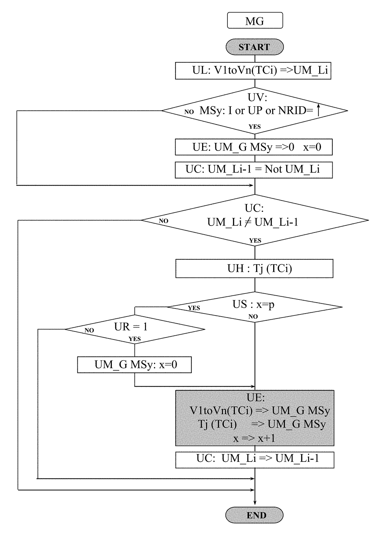
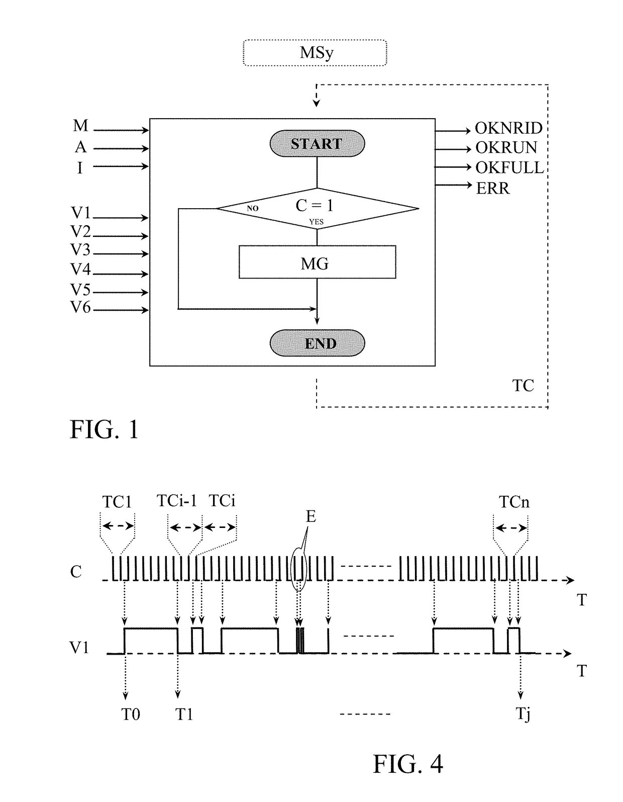
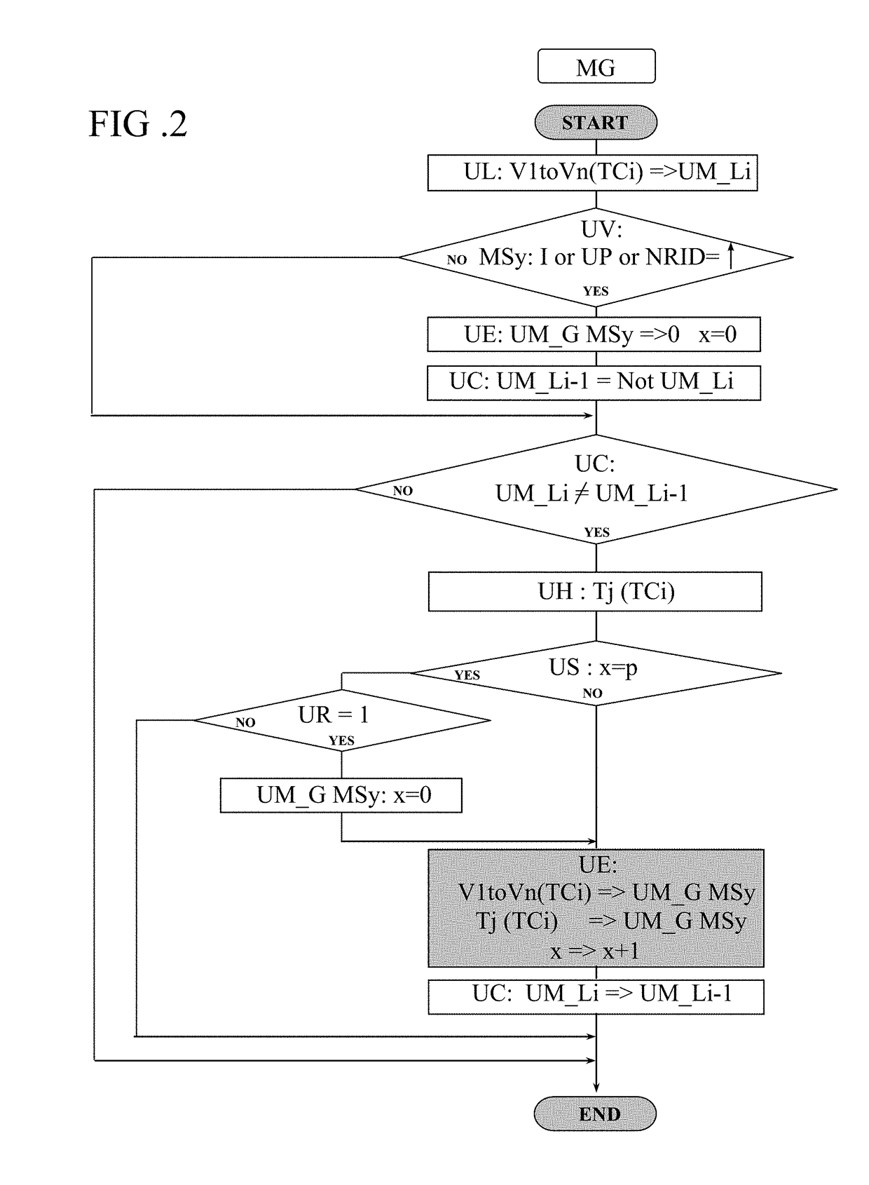
[0058]The monitoring and assessing method of this invention consists in implanting, directly in the user program itself of a controller C that drives an industrial installation, one or several specific monitoring modules MS1 to MSt, where t designates the total number of modules implanted, arranged to monitor all or a part of the internal variables of said user program. When talking of one single specific monitoring module, it is designated by MSy, where y is comprised between 1 and t. V1 to Vt designate the total number of variables monitored by all implanted specific monitoring modules MSy, and V1 to Vn designate the maximum number of variables monitored by each implanted specific monitoring module MSy. The whole of the monitored variables V1 to Vt can be equally inputs / outputs of sensors, components, machines, etc., internal variables of the user program, variables of the industrial installation, communication variables, etc., Boolean, numerical, complex (character string) variab...


PUM


Abstract

A method of monitoring and assessing program variables of an industrial installation driven by a controller (C) by instructions programmed in a user program. Specific monitoring modules (MS1 to MSt) are implanted, as close as possible in time to the variable(s) (V1 to Vt) to be monitored to monitor evolution in real-time. During execution, each specific monitoring module (MSy) reads, in real-time, the logic state of each of variables which it monitors in an instantaneous cycle turn (TCi) of the controller (C), compares this logic state with the previously recorded logic state, and, only in the case of a state change, records the new logic state read as well as the real-time time-stamp of this event in a global memory unit (UM_G). The recorded metadata is analyzed in order to check behavior of the installation, use this production data and identify a possible malfunction of program and / or the installation.

Description

[0001]This application is a National Stage completion of PCTEP2016 / 065336 filed Jun. 30, 2016, which claims priority from French patent application serial no. 15 / 56654 filed Jul. 13, 2015.FIELD OF THE INVENTION[0002]This invention relates to a method of monitoring and assessing an industrial installation driven by a programmable controller by means of instructions programmed in a user program of said controller, said user program comprising internal variables for coordinating the execution of said instructions at every indefinitely repeated cycle turn of said controller, allowing the operation of at least a section of said industrial installation.[0003]The invention also relates to an equipment for monitoring and assessing an industrial installation driven by a programmable controller that implements the method defined above.BACKGROUND OF THE INVENTION[0004]The industrial installations, which can be used in any kind of industries, are mainly driven by one or several programmable con...

Claims


Application Information

Patent Timeline
IPC IPC(8): G05B19/05
CPCG05B19/058G05B19/056G05B2219/24055G05B2219/24067
Inventor THABUIS, FREDERIC
Owner TLOGIC AUTOMATION
Learn More