Fcc yield selectivity improvements in high containment riser termination systems

a technology of high containment riser and yield selectivity, which is applied in the direction of catalytic cracking, chemical/physical processes, chemistry apparatus and processes, etc., can solve the problems of increasing the residence time between the hydrocarbon vapor and the catalyst, increasing the potential for lower hydrocarbon yield and greater catalyst fouling, and increasing the hydrocarbon underflow to the catalyst bed. , to achieve the effect of reducing the amount of undesired thermal and catalytic reactions, increasing the residence tim

Active Publication Date: 2018-07-26
MARATHON PETROLEUM
View PDF5 Cites 0 Cited by
  • Summary
  • Abstract
  • Description
  • Claims
  • Application Information

AI Technical Summary

Benefits of technology

[0004]This invention reduces the amount of undesired thermal and catalytic reactions occurring in FCC reactors having high containment separation systems such as the VSS / VDS. The undesired reactions are exacerbated by hydrocarbon underflow in the separation system, resulting in increased residence time between the hydrocarbon vapors and the catalyst. It is desirable to limit the time during which the hydrocarbon vapors and catalysts are intermixed. The longer the mixing time, the more potential for lower hydrocarbon yields and greater catalyst fouling. If the catalyst is too fully entrained with hydrocarbon vapors as it exits the riser and enters the separation technology, the hydrocarbon vapor will not cleanly separate from the catalyst and will carry under with the catalyst resulting in hydrocarbon underflow to the catalyst bed, leading to unwanted thermal and catalytic reactions. The present invention mitigates these unwanted reactions and improves FCC yield by minimizing hydrocarbon underflow into the separation system. In essence, the bottom of the separation system sits in a catalyst bed that prevents hydrocarbon vapor from remixing with the catalyst in the separation system. Vent tubes provide an exit path for the hydrocarbon vapor exiting the stripper to bypass the separation system and exit the reactor via the cyclones.
[0005]The cyclone operations must be carefully monitored to ensure that cyclone inlet hydrocarbons are not dragged downward by the catalytic solids. Historically, increasing the amount of catalyst inventory contained in the reaction prevents such under flow or back flow of hydrocarbon gases. However, the structures of the present invention create an environment wherein increased hydrocarbon gas yield can be associated with lesser catalyst inventory, less catalyst entrainment into the separation system and less resultant hydrocarbon underflow.

Problems solved by technology

The undesired reactions are exacerbated by hydrocarbon underflow in the separation system, resulting in increased residence time between the hydrocarbon vapors and the catalyst.
The longer the mixing time, the more potential for lower hydrocarbon yields and greater catalyst fouling.
If the catalyst is too fully entrained with hydrocarbon vapors as it exits the riser and enters the separation technology, the hydrocarbon vapor will not cleanly separate from the catalyst and will carry under with the catalyst resulting in hydrocarbon underflow to the catalyst bed, leading to unwanted thermal and catalytic reactions.

Method used


Image

  • Fcc yield selectivity improvements in high containment riser termination systems
  • Fcc yield selectivity improvements in high containment riser termination systems
  • Fcc yield selectivity improvements in high containment riser termination systems

Examples


Embodiment Construction

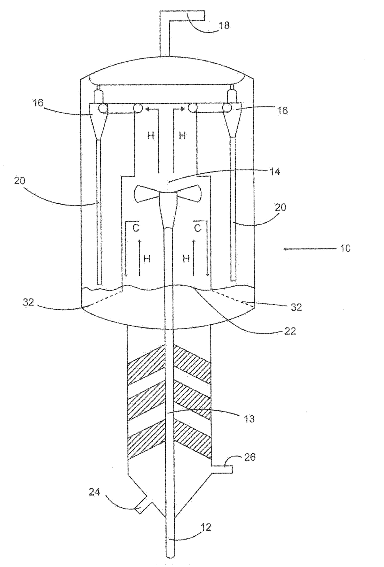
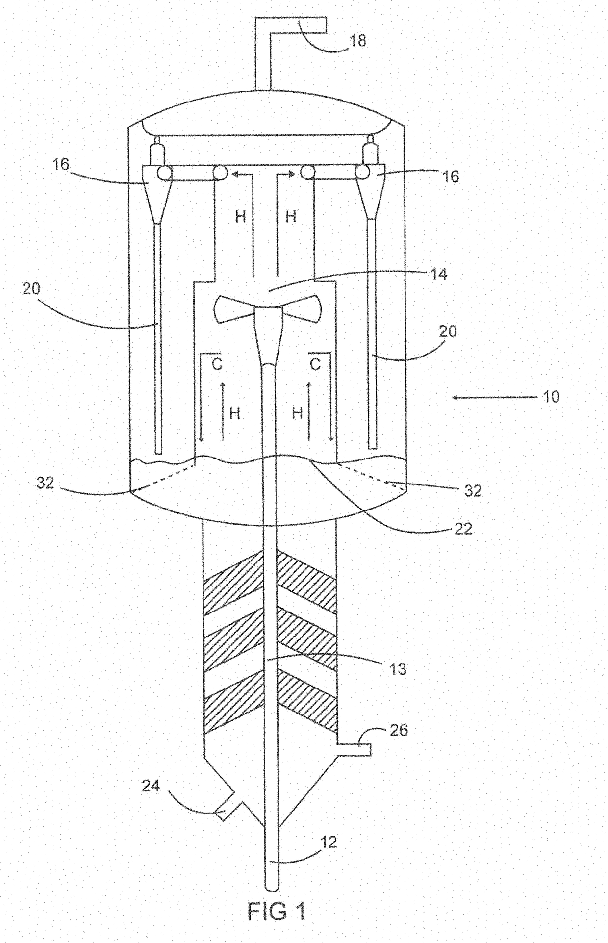
[0016]Referring now to FIG. 1, a schematic depicting a FCC reactor incorporating a first embodiment of the invention is shown having a lowered fluidized catalyst bed 22 maintained just above the windows 32 of the separator or VSS 14. The reactor 10 includes an inlet 12 for receiving a mixture of heated crude oil and heated catalyst. The crude and catalyst mixture travels up the riser 13 during which the catalyst and crude internet and the catalyst absorbs carbon, metals, and other deleterious materials not wanted in the hydrocarbon gases. As the entrained hydrocarbon / catalyst mixture exits the riser and enters the separator 14 the catalyst will fall downward through the separator 14 while the clean hydrocarbon stream continues to rise where it is received by cyclones 16 which serve to further separate any remaining catalyst from the hydrocarbon stream. The cleansed hydrocarbon stream then exits the reactor through outlet 18 to be transferred to separation equipment, such as a fracti...


PUM

PropertyMeasurementUnit
bed densityaaaaaaaaaa

Abstract

The invention provides an improved system for separation technology intended to reduce unwanted catalyst / thermal reactions by minimizing contact of the hydrocarbons and the catalyst within the reactor.

Description

CROSS REFERENCE TO RELATED APPLICATION[0001]The present patent application is based upon and claims the benefit of provisional patent application No. 62 / 430,512, filed on Dec. 6, 2016.BACKGROUND OF THE INVENTION[0002]Fluidic catalytic cracker (FCC) reactor technology has evolved over the years, continuously searching to improve yield selectivity of hydrocarbons by minimizing unwanted reactions that occur outside of the FCC riser. Most FCC reactors use a catalyst which is an extremely porous powder that reacts with the hydrocarbon mixture to capture intermetal carbon and metal. In the process, the pre-heated hydrocarbon feed mixed with hot catalyst enters the reactor through one or more risers. The riser creates a fluidized bed where a concurrent upward flow of reactant gases and catalyst particles occurs. Nearly every FCC unit employs some type of separation device connected on the end of the riser which is intended to separate the bulk of the catalyst from the hydrocarbon vapors. T...

Claims


Application Information

Patent Timeline
Patent Type & Authority Applications(United States)
IPC IPC(8): C10G11/20B01J8/00B01J8/18B01J8/34
CPCC10G11/20B01J8/0025B01J8/0055B01J8/008B01J8/1872B01J8/34B01J2208/00557B01J2208/0061B01J2208/00929B01J2219/00763
Inventor LARSEN, NIKOLASSEXTON, JEFF
Owner MARATHON PETROLEUM
Why Eureka
Try Eureka