Common mode filter and manufacturing method thereof
- Summary
- Abstract
- Description
- Claims
- Application Information
AI Technical Summary
Benefits of technology
Problems solved by technology
Method used
Image

Examples
first embodiment
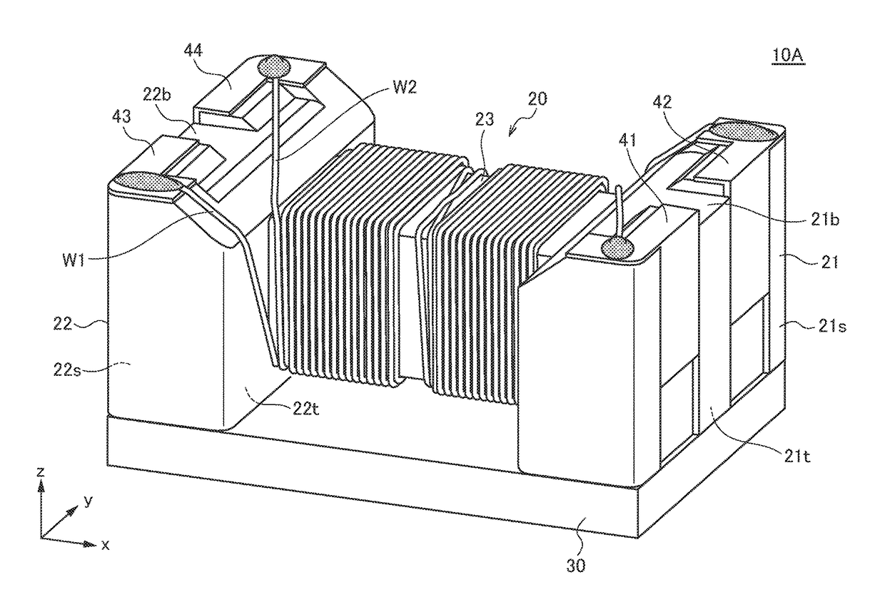
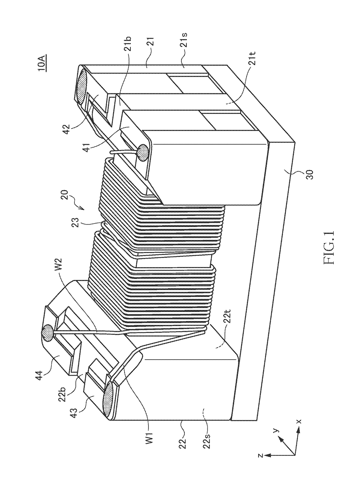
[0042]FIG. 1 is a schematic perspective view illustrating the outer appearance of a common mode filter 10A according to the first embodiment of the present invention.
[0043]As illustrated in FIG. 1, the common mode filter 10A according to the present embodiment has a drum-shaped core 20, a plate-like core 30, first to fourth terminal electrodes 41 to 44, and first and second wires W1 and W2. The drum-shaped core 20 and the plate-like core 30 are each formed of a magnetic material having a comparatively high permeability, such as an Ni—Zn based ferrite. The first to fourth terminal electrodes 41 to 44 are each a metal fitting formed of a good conductor material such as copper.
[0044]The drum-shaped core 20 has a first flange part 21, a second flange part 22, and a winding core part 23 disposed between the first and second flange parts 21 and 22. The winding core part 23 has its axis direction in the x-direction. The first and second flange parts 21 and 22 are disposed at the axially bo...
second embodiment
[0062]FIG. 9 is a schematic perspective view illustrating the outer appearance of a common mode filter 10B according to the second embodiment of the present invention.
[0063]As illustrated in FIG. 9, the common mode filter 10B according to the present embodiment differs from the common mode filter 10A according to the first embodiment in the layout of the second wire W2. Other configurations are the same as those of the common mode filter 10A according to the first embodiment, so the same reference numerals are given to the same elements, and overlapping description will be omitted.
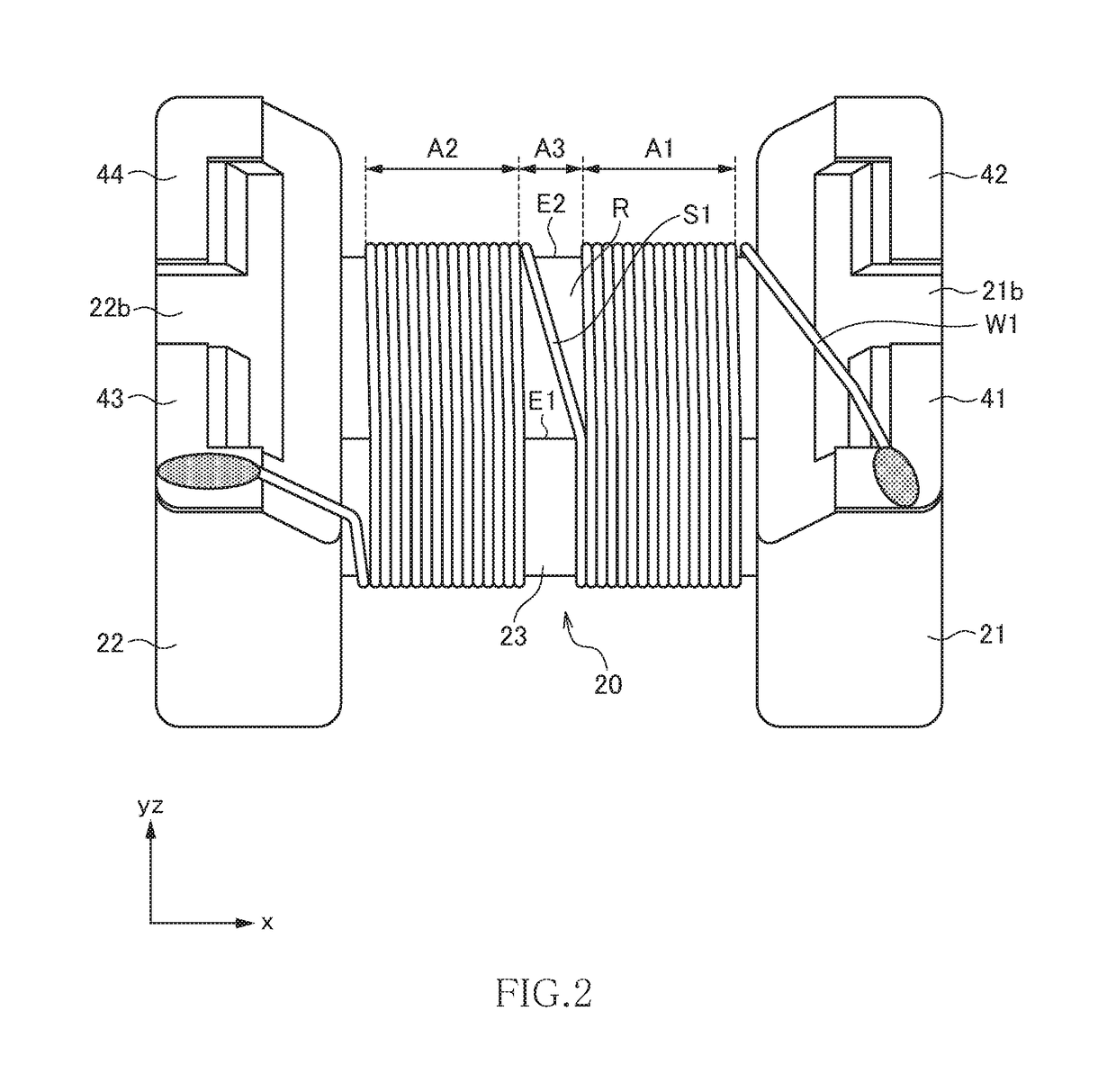
[0064]FIG. 10 is a schematic view for explaining more in detail the winding layout of the first and second wires W1 and W2. FIG. 11A is a schematic cross-sectional view taken along line A-A (second edge E2) shown in FIG. 10, FIG. 11B is a schematic cross-sectional view taken along line B-B shown in FIG. 10, and FIG. 11C is a schematic cross-sectional view taken along line C-C (first edge E1) shown in FIG. ...
third embodiment
[0070]FIG. 12 is a schematic perspective view illustrating the outer appearance of a common mode filter 10C according to the third embodiment of the present invention.
[0071]As illustrated in FIG. 12, the common mode filter 10C according to the present embodiment differs from the common mode filter 10B according to the second embodiment in that the yz cross section of the winding core part 23 has a hexagonal shape and, thus, a third edge E3 exists between the first and second edges E1 and E2. Other configurations of the common mode filter 10C are the same as those of the common mode filter 10B according to the second embodiment, so the same reference numerals are given to the same elements, and overlapping description will be omitted.
[0072]The third edge E3 exists at substantially an intermediate position between the first and second edges E1 and E2. That is, a distance between the third edge E3 and the first edge E1 in the y-direction is substantially equal to a distance between the...
PUM
 Abstract
Description
Claims
Application Information
 - Generate Ideas
- Intellectual Property
- Life Sciences
- Materials
- Tech Scout
- Unparalleled Data Quality
- Higher Quality Content
- 60% Fewer Hallucinations
Browse by: Latest US Patents, China's latest patents, Technical Efficacy Thesaurus, Application Domain, Technology Topic, Popular Technical Reports.
© 2025 PatSnap. All rights reserved.Legal|Privacy policy|Modern Slavery Act Transparency Statement|Sitemap|About US| Contact US: help@patsnap.com