
Method and device for processing video signal

a video signal and processing method technology, applied in the field of methods and devices for processing video signals, can solve the problems of increased transmission cost and storage cost, and achieve the effects of improving the efficiency of prediction or restoration of blocks, reducing the cost of storage, and improving the efficiency of palette entry encoding/decoding efficiency

Inactive Publication Date: 2018-07-26
KT CORP
View PDF9 Cites 8 Cited by
  • Summary
  • Abstract
  • Description
  • Claims
  • Application Information

AI Technical Summary

Benefits of technology

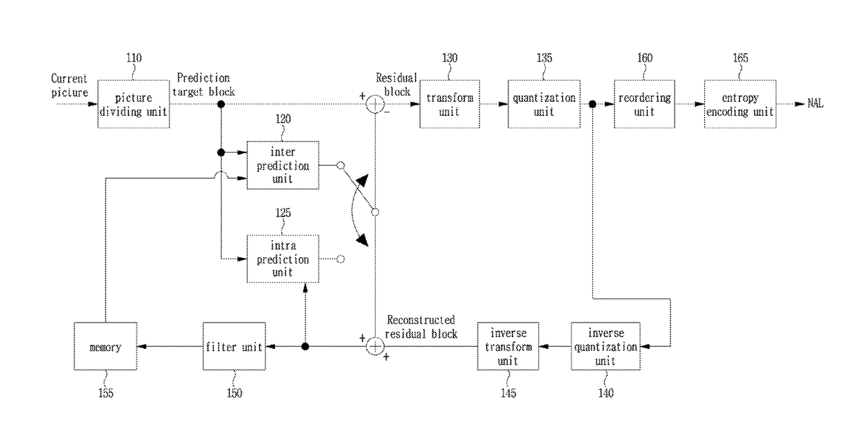
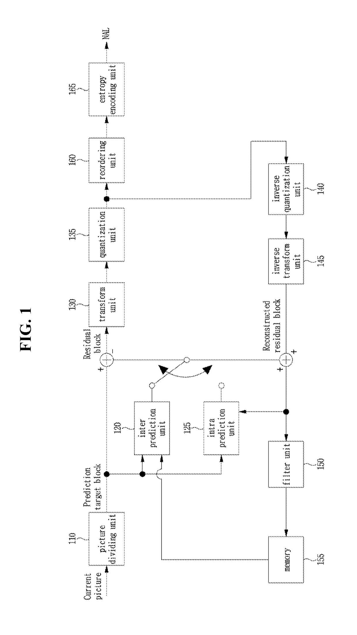
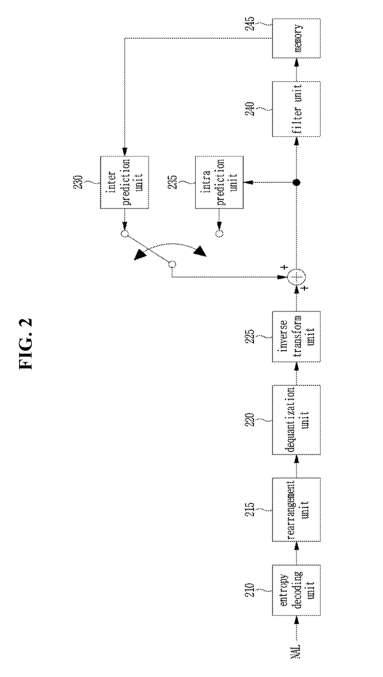
The present invention improves the efficiency of predicting, restoring, and encoding / decoding of blocks using a palette mode. By analyzing the palette map of a previous block, the invention derives a more accurate palette map for the current block, leading to improved efficiency in predicting and restoring block details. The invention also improves compression efficiency by encoding the palette index using a binary vector based on run encoding and restoring sample values based on the escape mode. Additionally, the invention adaptively encodes / decodes a palette mode type flag to further improve compression efficiency.

Problems solved by technology

Therefore, if video data is transmitted on an existing medium such as a wired / wireless wideband circuit or stored in an existing storage medium, transmission cost and storage cost increase.

Method used


Image

  • Method and device for processing video signal
  • Method and device for processing video signal
  • Method and device for processing video signal

Examples


embodiment 1

Palette_Type_Run

[0296]In this embodiment, as shown in FIG. 22, it is assumed that the palette mode types used in the current block are arranged in the order of INDEX MODE (CI), CI, COPY MODE (CA), CI, CI, CI, CA, CI, CA, CI, . . . .

[0297]Referring to FIG. 22, if the number of INDEX MODEs between the first sample in the current block and the sample in which the COPY MODE firstly occurs in the current block is n, n may be encoded as a value of palette_type_run corresponding thereto. On the other hand, if the number of INDEX MODEs between samples in which COPY MODE occurs is m, (m−1) may be encoded with a value of palette_type_run corresponding thereto.

[0298]Thus, if the first signaled palette_type_run value is n, this could mean that the number of INDEX MODEs between the first sample of the current block and the sample in which COPY mode firstly occurs in the current block is n. On the other hand, if the value of the palette_type_run signaled second or thereafter is m, it means that t...

embodiment 2

MSB and Refinement Bit

[0302]PaletteTypeRun may be encoded using the MSB and the refinement bit. For this purpose, the syntax palette_type_run_msb_id_plus1 indicating the MSB and the syntax palette_type_run_refinement_bits indicating the refinement bit may be used. For example, if palette_type_run_msb_id_plus1 is 0 or 1, PaletteTypeRun may be set to the same value as palette_type_run_msb_id_plus1. On the other hand, if palette_type_run_msb_id_plus1 is greater than 1, PaletteTypeRun may be derived as shown in Equation 3 below.

PaletteTypeRun=(1<<(palette.type.run.msb.id.plus1+1))+palette.type.run.refinement.bits  [Equation 3]


PUM


Abstract

A video signal processing method according to the present invention is characterized by constructing a palette map relating to a current block encoded in a palette mode, deriving a number of palette indices encoded according to an index mode (INDEX MODE), determining palette index relating to the current block based on the derived number of palette indices, and reconstructing the current block based on the palette map and the palette index.

Description

TECHNICAL FIELD[0001]The present invention relates to a method and a device for processing a video signal.BACKGROUND ART[0002]Demands for high-resolution, high-quality images such as High Definition (HD) images and Ultra High Definition (UHD) images have recently increased in various fields of applications. As video data has a higher resolution and higher quality, the video data is larger in amount than traditional video data. Therefore, if video data is transmitted on an existing medium such as a wired / wireless wideband circuit or stored in an existing storage medium, transmission cost and storage cost increase. To avert these problems encountered with higher-resolution, higher-quality video data, high-efficiency video compression techniques may be used.[0003]There are a variety of video compression techniques including inter-picture prediction in which pixel values included in a current picture are predicted from a picture previous to or following the current picture, intra-pictur...

Claims


Application Information

Patent Timeline
Patent Type & Authority Applications(United States)
IPC IPC(8): H04N19/103H04N19/129H04N19/159H04N19/176
CPCH04N19/176H04N19/70H04N19/103H04N19/129H04N19/159H04N19/50H04N19/593H04N19/93
Inventor LEE, BAE KEUNKIM, JOO YOUNG
Owner KT CORP
Learn More