Rotatable thruster aircraft with separate lift thrusters

a technology of thruster and thruster, which is applied in the direction of aircraft, vehicles, vertical landing/take-off aircraft, etc., can solve the problems of using propulsion systems and having to carry one system

Inactive Publication Date: 2018-08-02
RENTERIA JOSEPH RAYMOND
View PDF0 Cites 42 Cited by
  • Summary
  • Abstract
  • Description
  • Claims
  • Application Information

AI Technical Summary

Problems solved by technology

The disadvantage of tilt rotors is that they must use propulsion systems which are not optimized for either vertical or horizontal flight.
The drawback here is that one system must carry the other as dead weight when not in use.

Method used


Image

  • Rotatable thruster aircraft with separate lift thrusters
  • Rotatable thruster aircraft with separate lift thrusters
  • Rotatable thruster aircraft with separate lift thrusters

Examples


Embodiment Construction

[0064]Before describing the invention in detail, it should be observed that the present invention resides primarily in a novel and non-obvious combination of elements and process steps. So as not to obscure the disclosure with details that will readily be apparent to those skilled in the art, certain conventional elements and steps have been presented with lesser detail, while the drawings and specification describe in greater detail other elements and steps pertinent to understanding the invention.

[0065]The following embodiments are not intended to define limits as to the structure or method of the invention, but only to provide exemplary constructions. The embodiments are permissive rather than mandatory and illustrative rather than exhaustive.

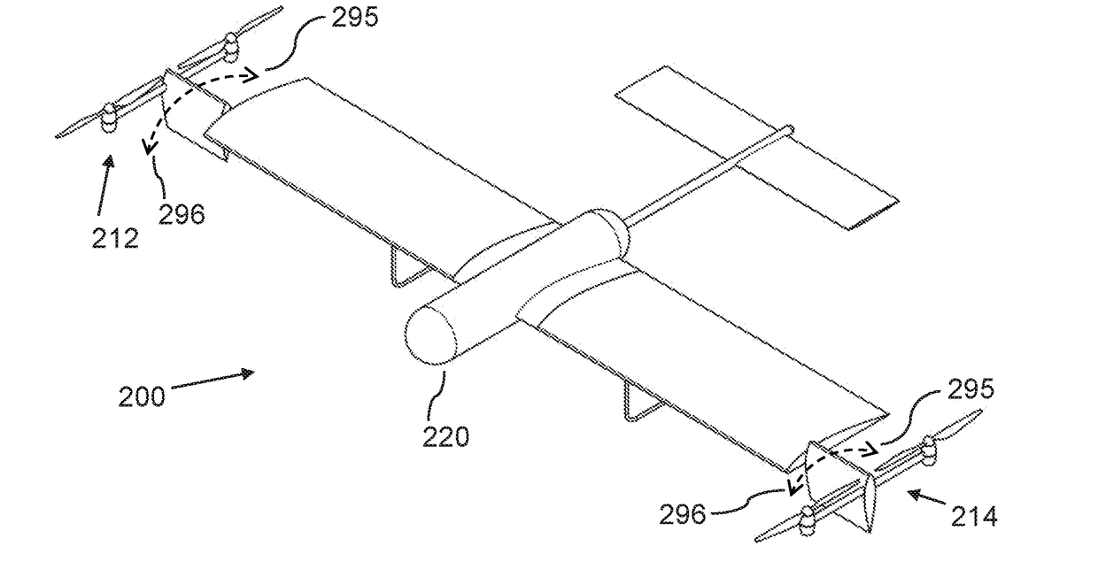
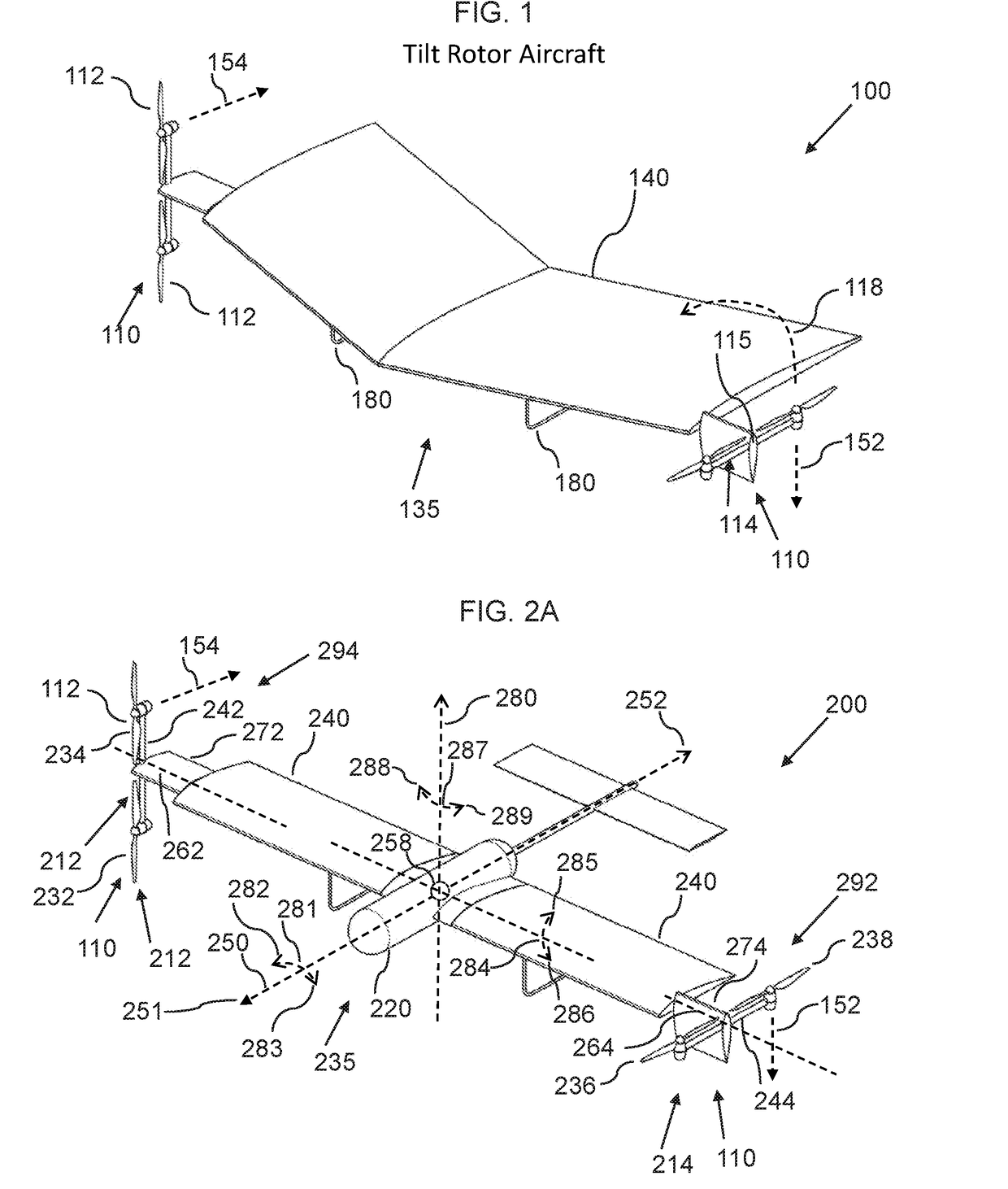
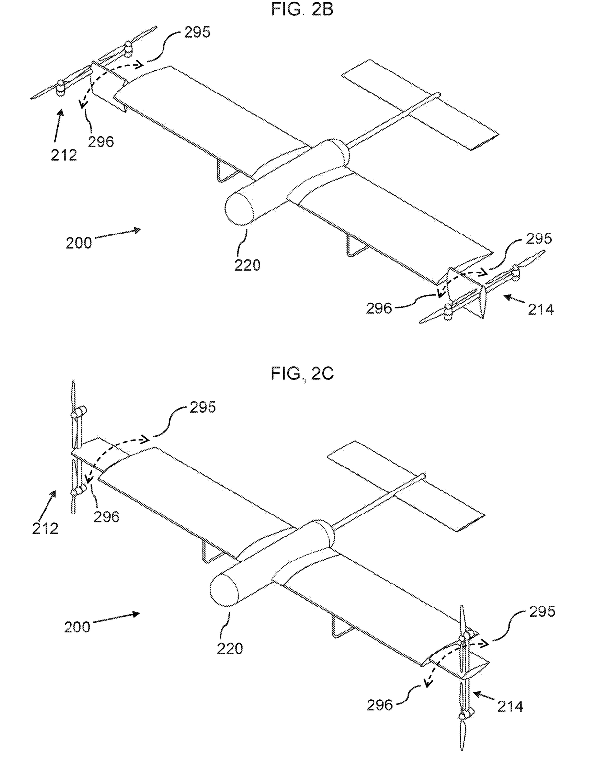
[0066]In the following, we describe the structure of an embodiment of a rotatable thruster aircraft 100 with reference to FIG. 1, in such manner that like reference numerals refer to like components throughout; a convention that we shall emp...


PUM


Abstract

A rotatable thruster aircraft includes a fixed wing; rotatable thruster assemblies, each including first and second thrusters that provide rotation via differential thrust; and vertical lift thrusters, optionally connected via an elongated member; and an aircraft control unit, including a processor, a non-transitory memory, an input/output component, and a power manager that controls specific power applied to the thrusters.

Description

CROSS-REFERENCE TO RELATED APPLICATIONS[0001]This application claims the benefit of U.S. Provisional Application No. 62 / 452,781, filed Jan. 31, 2017, which is hereby included herein by reference in its entirety.FIELD OF THE INVENTION[0002]The present invention relates generally to the field of propulsion systems for VTOL aircraft, and more particularly to methods and systems for hybrid propulsion aircraft including a set of dedicated vertical lift thrusters and a set of rotatable thruster assemblies, which are able to provide lift during both vertical and horizontal flight.BACKGROUND OF THE INVENTION[0003]In the world of aviation there are many different types of VTOL / fixed wing systems. So far, the most successful designs have been tilt rotor craft, which have the advantage of using one propulsion system through all envelopes of flight. The disadvantage of tilt rotors is that they must use propulsion systems which are not optimized for either vertical or horizontal flight. Separate...

Claims


Application Information

Patent Timeline
Patent Type & Authority Applications(United States)
IPC IPC(8): B64C29/00B64C25/10B64C27/02B64C27/26B64C27/28
CPCB64C29/0033B64C25/10B64C27/02B64C27/26B64C27/28B64C27/04B64C27/20B64C29/0025Y02T50/40
Inventor RENTERIA, JOSEPH RAYMOND
Owner RENTERIA JOSEPH RAYMOND
Why Eureka
Try Eureka