Supercharge Your Innovation With Domain-Expert AI Agents!

Gas turbine engine architecture with split compressor system

a compressor system and gas turbine engine technology, applied in the field of gas turbine engines, can solve problems such as complicated engine disassembly procedures

Inactive Publication Date: 2018-08-02
PRATT & WHITNEY CANADA CORP
View PDF15 Cites 19 Cited by
  • Summary
  • Abstract
  • Description
  • Claims
  • Application Information

AI Technical Summary

Benefits of technology

The patent describes a gas turbine engine design that includes a low pressure compressor, high pressure compressor, high pressure turbine, and low pressure turbine that are all connected in series by a core gaspath. The engine also includes an external shaft that connects the low pressure turbine to the low pressure compressor. This design allows for more efficient engine performance, with improved fuel efficiency and power output.

Problems solved by technology

However, in some instances, concentric shaft arrangements such as the one described above may complicate the engine disassembly procedures.

Method used


Image

  • Gas turbine engine architecture with split compressor system
  • Gas turbine engine architecture with split compressor system
  • Gas turbine engine architecture with split compressor system

Examples


Embodiment Construction

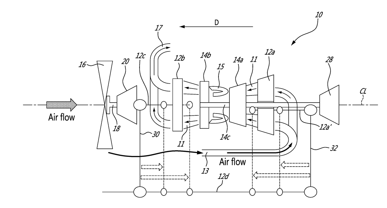
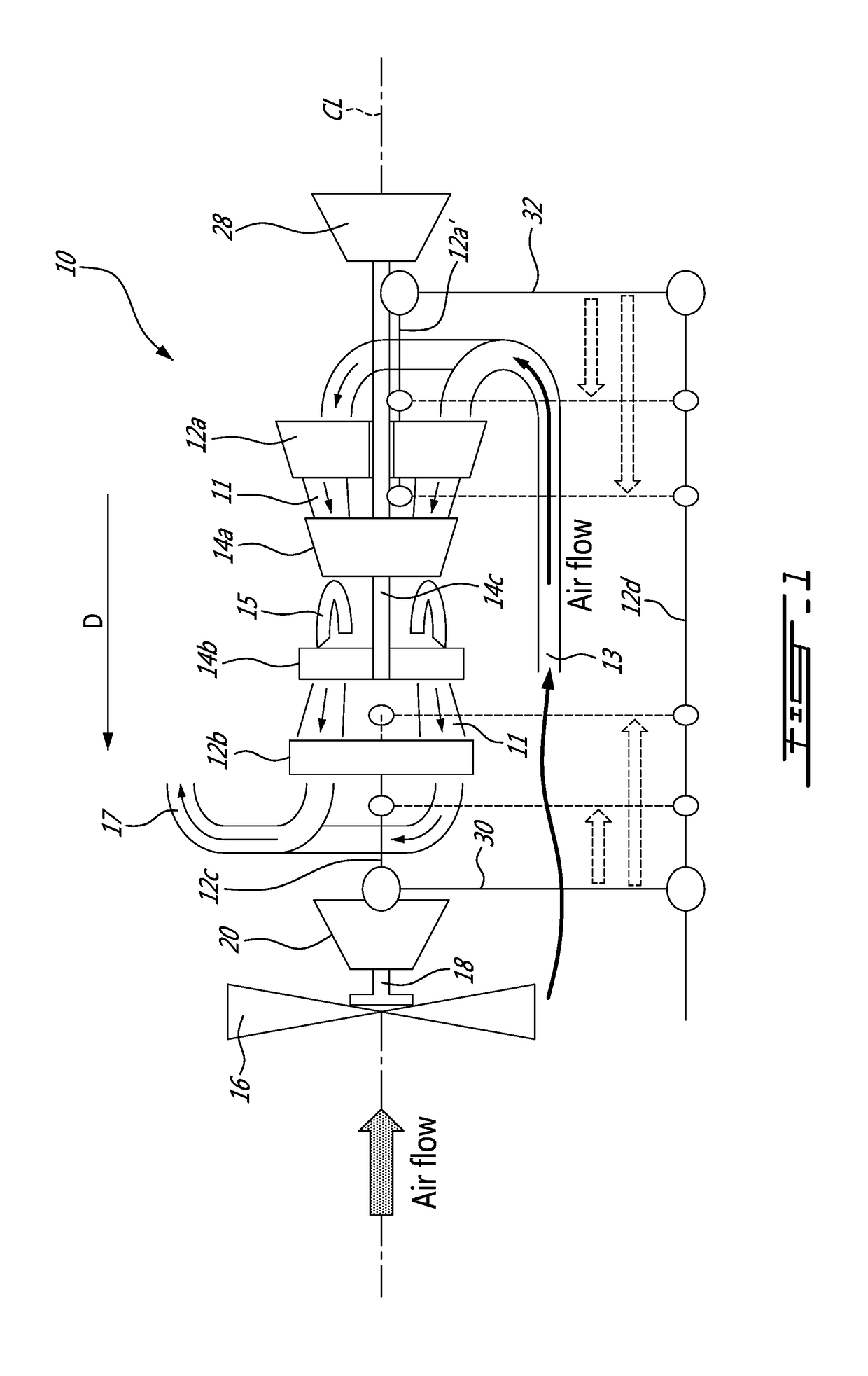
[0013]FIG. 1 illustrates a first example of a multi-spool gas turbine engine 10 of a type preferably provided for use in subsonic flight, and generally comprising an engine core having a turbomachinery with multiple spools which perform compression to pressurize atmospheric air received through an air inlet 13, and which extract energy from combustion gases before they exit the engine via an exhaust outlet 17. The engine core further comprises a core gaspath 11 to direct gases from the air inlet 13 to the exhaust outlet 17, as depicted by the flow arrows in FIG. 1. The core gaspath 11 may be annular and concentric relative to the engine centerline CL.

[0014]The term “spool” is herein intended to broadly refer to drivingly connected turbine and compressor rotors and is, thus, not limited to a compressor and turbine assembly on a single shaft. As will be seen hereinafter, it also includes a rotary assembly with multiple shafts geared together.

[0015]In the embodiment shown in FIG. 1, th...


PUM


Abstract

A gas turbine engine has an engine core including a low pressure compressor, a high pressure compressor, a high pressure turbine and a low pressure turbine coaxially mounted about an engine axis and fluidly connected in series by a core gaspath. The low pressure turbine is drivingly connected to the low pressure compressor via an external shaft disposed radially outwardly of the core gaspath.

Description

TECHNICAL FIELD[0001]The application relates generally to gas turbine engines and, more particularly, to a multi-spool engine architecture having a split compressor system.BACKGROUND OF THE ART[0002]Many gas turbine engine architectures with multiple stages have a low pressure compressor, high pressure compressor, high pressure turbine and low pressure turbine arranged sequentially in this order along the engine axial direction. The low pressure compressor at a first end of the engine is drivingly connected to the low pressure turbine at the opposed end of the engine via a low pressure shaft extending concentrically through a hollow high pressure shaft, which, in turn, drivingly connects the high pressure turbine to the high pressure compressor.[0003]For reasons, such as maintainability and reparability, it is generally desirable to have an engine architecture that allows for simple engine disassembly. However, in some instances, concentric shaft arrangements such as the one describ...

Claims


Application Information

Patent Timeline
Patent Type & Authority Applications(United States)
IPC IPC(8): F02C3/107F02C7/36B64D27/10
CPCF02C3/107F02C7/36F05D2260/40311F05D2220/325B64D27/10F05D2260/4031F05D2250/312Y02T50/60
Inventor PLANTE, GHISLAINVALOIS, PATRICKDUBREUIL, JEANBLAIS, DANIEL
Owner PRATT & WHITNEY CANADA CORP
Features
  • R&D
  • Intellectual Property
  • Life Sciences
  • Materials
  • Tech Scout
  • Unparalleled Data Quality
  • Higher Quality Content
  • 60% Fewer Hallucinations
Learn More