Light-Weight Headlamp

Inactive Publication Date: 2018-08-02
E MISHAN & SONS
View PDF1 Cites 3 Cited by
  • Summary
  • Abstract
  • Description
  • Claims
  • Application Information

AI Technical Summary

Benefits of technology

[0006]It is an object of the present invention to provide a light-weight headlamp that uses plastic, non-conductive materials in the interior structure of its light source housing, rather than heavier thermally conductive m

Problems solved by technology

While likely effective in channeling the substantial amount of heat generated by LED light sources, forward and thus away for the wearer's head, by u

Method used


Image

  • Light-Weight Headlamp
  • Light-Weight Headlamp
  • Light-Weight Headlamp

Examples


Embodiment Construction

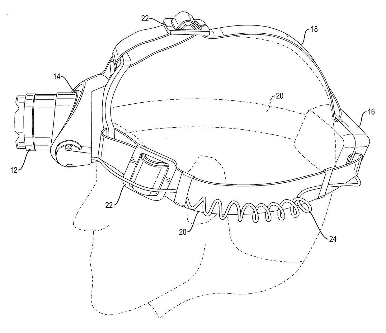
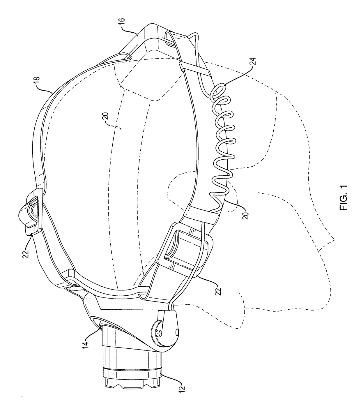
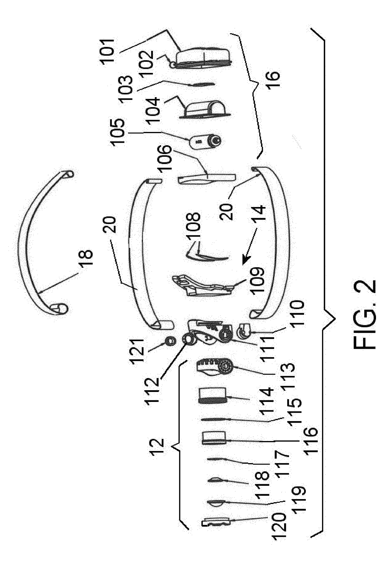
[0014]Referring now to the drawings, in which like reference numerals are used to refer to the same or similar elements, FIG. 1 shows a light-weight headlamp of the invention, which includes a light source housing 12 containing at least one SMD LED for generating light when energized, a mount assembly 14 for pivotally carrying the light source housing, a power source housing 16 adapted to containing an electrical power source, at least one, but preferable three strap 18 and 20, connected between the mount assembly 14 and the power source housing 16 and adapted to hold the mount assembly and the power source housing to a users head and a connecting wire 24 for electrically connecting the power source housing 16 to the SMD LED for energizing the SMD LED with electrical power from the power source in the power source housing 16, to generate light.

[0015]In a preferred embodiment of the invention, the straps are a cloth and elastic blend so as to be stretchable, with adjusting buckets 22...


PUM


Abstract

A light-weight headlamp has a housing containing at least one SMD LED mounted to a circuit board on an inner housing made of thermally non-conductive material fixed to and disposed partly in a pivot mount. The pivot mount is pivotally connected to a mount assembly that is connected by one or more straps to a power source housing containing an electrical power source. The straps hold the mount assembly and power source housing to a users head and a wire connects the power source to the SMD LED. A shield disposed partly in the pivot mount is slidably engaged over the inner housing. A bezel with lens is connected to the shield and changes the shape of a light beam from the SMD LED as the shield slides on the inner housing.

Description

FIELD AND BACKGROUND OF THE INVENTION[0001]The present invention relates generally to the field of battery powered portable lights, and in particular to a light-weight headlamp for hands-free lighting of an area in front of a wearer of the headlamp.[0002]U.S. Pat. Nos. 7,513,660 and 7,918,578 to Spartano et al. disclose a headlamp having various useful features such and a pivotable light source housing for aiming the beam of light, and a telescopic lens arrangement in the housing for focusing and spreading the beam of light from an LED light source in the housing.[0003]Due to the substantial heat generated by LEDs, these patents also seeks to transfer this heat forwardly and away from the wearer's forehead, by including an internal structure having an inner thermally conductive heat sink in thermal relationship with the LED light source, and an outer heat sink member in thermal heat transfer relationship with the inner heat sink, disposed generally forward of a rear end of the headl...

Claims


Application Information

Patent Timeline
IPC IPC(8): F21V21/084F21V21/30F21V23/02F21V23/00F21V5/04F21L4/06F21V31/00
CPCF21V21/084F21V21/30F21V23/023F21V23/001F21V23/0414F21L4/06F21V31/005F21Y2115/10F21V7/041F21V5/04F21V21/0816F21V29/507F21V29/83
Inventor MISHAN, EDWARD I.
Owner E MISHAN & SONS
Why Eureka
Try Eureka