Heat exchanger

a technology of heat exchanger and burner, which is applied in the direction of furnace components, combustion process, lighting and heating apparatus, etc., can solve the problem that the door cannot be equipped with a small burner

Inactive Publication Date: 2018-08-02
SERMETA
View PDF11 Cites 2 Cited by
  • Summary
  • Abstract
  • Description
  • Claims
  • Application Information

AI Technical Summary

Problems solved by technology

However, such a door can only be equipped with a small-sized burner, b

Method used


Image

  • Heat exchanger
  • Heat exchanger
  • Heat exchanger

Examples


Embodiment Construction

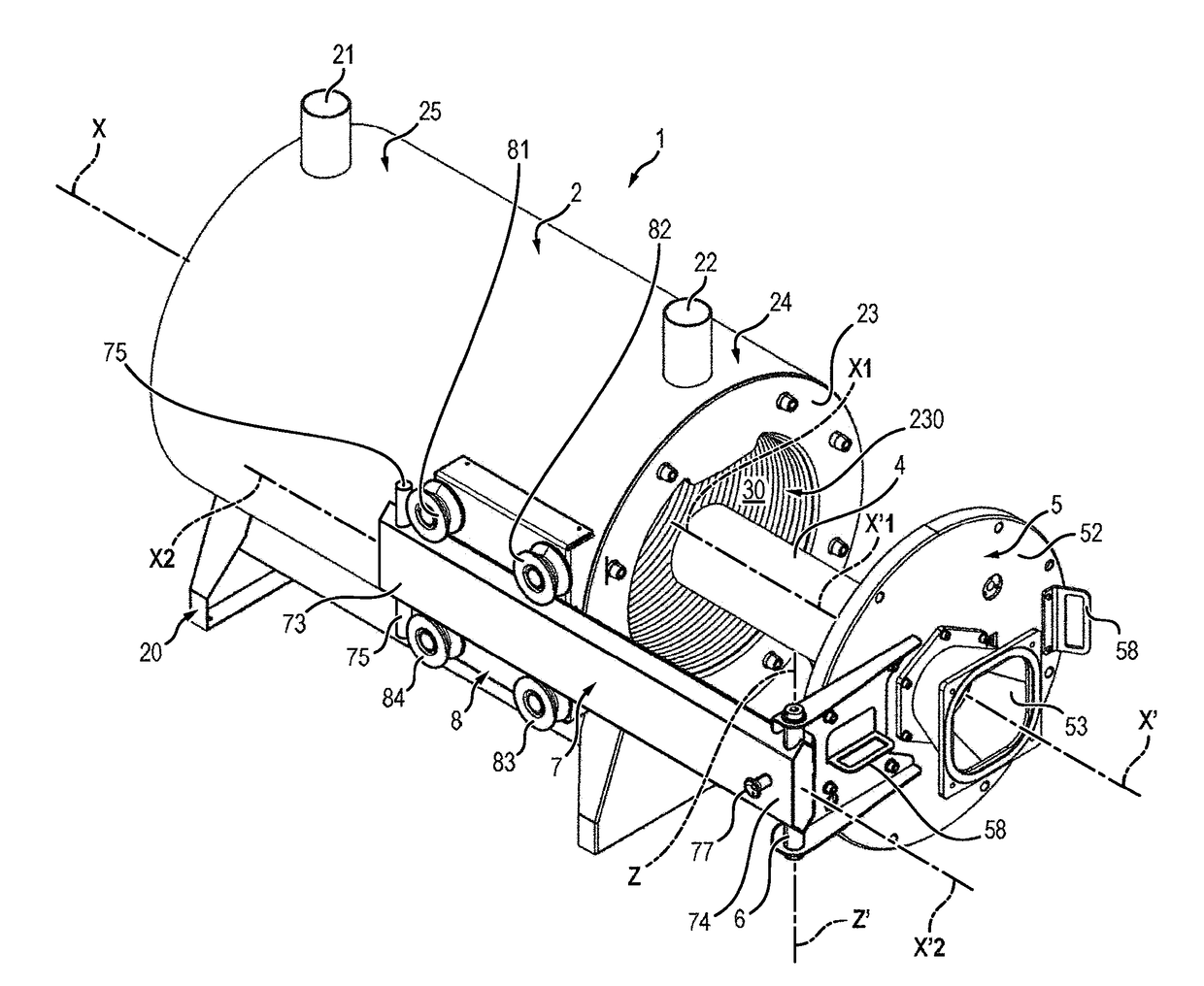
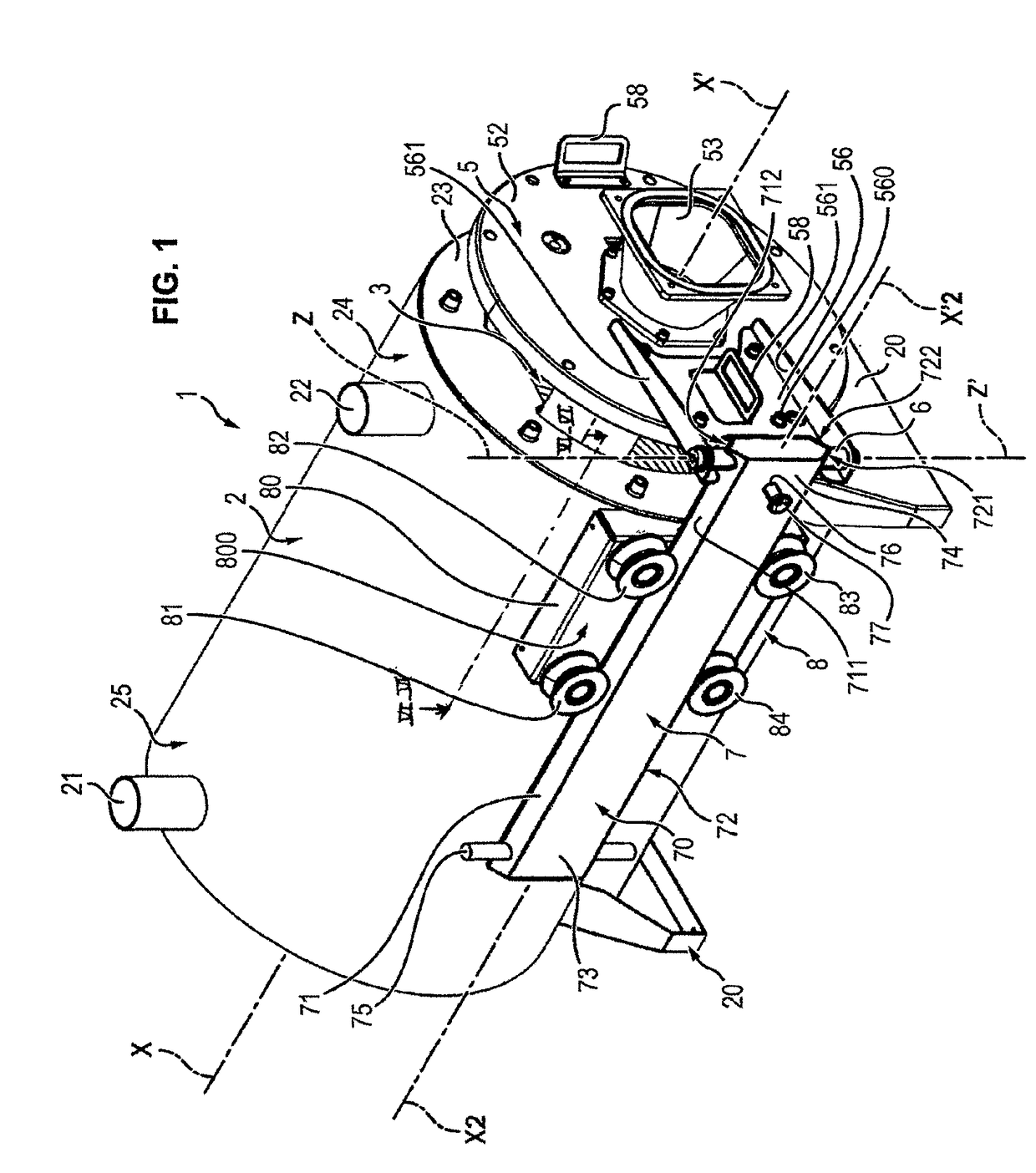
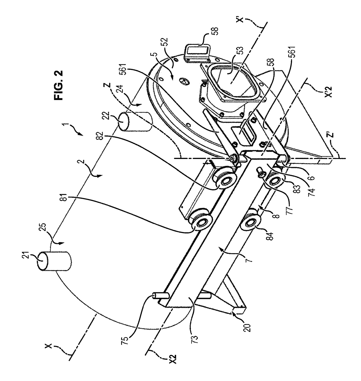
[0027]Referring back to FIG. 1, it can be seen that the heat exchanger 1 conforming to the invention comprises a gas-tight shell 2. This rests for example on legs 20.

[0028]In the rest of the description and of the claims, references to the terms “horizontal” or vertical will be taken into consideration with respect to the position of the exchanger 1 in FIGS. 1 to 5.

[0029]The shell 2 contains a heat exchange device 3 allowing a fluid, for example cold water, to be heated.

[0030]In the figures, reference symbols 21 and 22 correspond to the inlet and outlet apertures of the device 3 of the heat exchanger.

[0031]The shape of the shell 2 is immaterial (indifferent). It has a longitudinal axis X-X′. In the example shown in the figures, this shell 2 is cylindrical. It also has a burnt gas discharge sleeve, not visible in the figures.

[0032]The shell 2 has a face 23 which delimits an opening 230 for access to the interior of said shell. By convention, the end of the shell 2 situated in proximi...


PUM


Abstract

The invention relates to a heat exchanger (1) comprising a shell (2) containing a heat exchange device (3) and delimiting a combustion chamber (30), said shell (2) being provided with an access opening and with a door (5) provided on its inner face with a burner (4).
It is remarkable in that said door (5) is mounted pivotally around a pivot (6) attached to the end of a slide (7), in that said shell (2) is provided on its exterior surface with axial guide means (8) of said slide (7) along a displacement axis X2-X′2 which extends parallel to the longitudinal axis X-X′ of said shell (2), in that the pivot (6) extends along an axis Z-Z′ perpendicular to said displacement axis X2-X′2, the travel of said slide (7) being greater than the length of the burner (4).

Description

GENERAL TECHNICAL FIELD[0001]The invention is situated in the field of heat exchangers, particularly for a gas- or fuel oil-fired boiler.[0002]The present invention relates more precisely to a heat exchanger comprising a gas-tight shell containing a heat exchange device and delimiting a combustion chamber, said shell being provided with an access opening and with a door suitable for being able to close said access opening, said door being provided with a burner, particularly for gas or fuel oil, protruding from its inner face.PRIOR ART[0003]Also known already from document FR2942866 is a heat exchanger as previously mentioned. Its door is also provided on its outer face with a system for bringing a combustible mixture to the burner. Finally, said shell is provided with a sleeve for discharging the burned gasses.[0004]This door is attached detachably to a framework for said access opening, for example by means of screws.[0005]However, it is necessary to regularly gain access to the t...

Claims


Application Information

Patent Timeline
IPC IPC(8): F23C5/02F23C3/00F23D99/00F27D1/18
CPCF23C5/02F23C3/002F23D91/04F27D1/1808F27D2001/1825F27D2201/00F24H1/145F24H9/02F24H9/1836F23M5/08F23M7/00F24H1/43F24H9/0042F28F9/02
Inventor LE MER, JOSEPH
Owner SERMETA
Why Eureka
Try Eureka