Projection lens and projector

a projection lens and projector technology, applied in the direction of projectors, mountings, instruments, etc., can solve the problems of increasing the length of the entire lens, and achieving the compactness in the longitudinal direction, so as to achieve accurate assembly, reduce the size, and widen the angle

Active Publication Date: 2018-08-02
FUJIFILM CORP
View PDF1 Cites 17 Cited by
  • Summary
  • Abstract
  • Description
  • Claims
  • Application Information

AI Technical Summary

Benefits of technology

[0018]According to the present invention, it is possible to provide a projection lens and a projector which are capable of being accurately assembled while achieving a reduction in size, and are capable of widening an angle by reducing a focal length.

Problems solved by technology

However, WO09 / 107553A and JP2006-330410A have an adverse effect that the entire lens length increases due to an intermediate image being formed one time.
However, a length in a traverse direction, for example, is shortened as much as the optical axis is bent simply by inserting one mirror, but a length in a longitudinal direction is lengthened as much as the optical axis is bent, which leads to no achievement in compactness in a longitudinal direction.

Method used


Image

  • Projection lens and projector
  • Projection lens and projector
  • Projection lens and projector

Examples


first embodiment

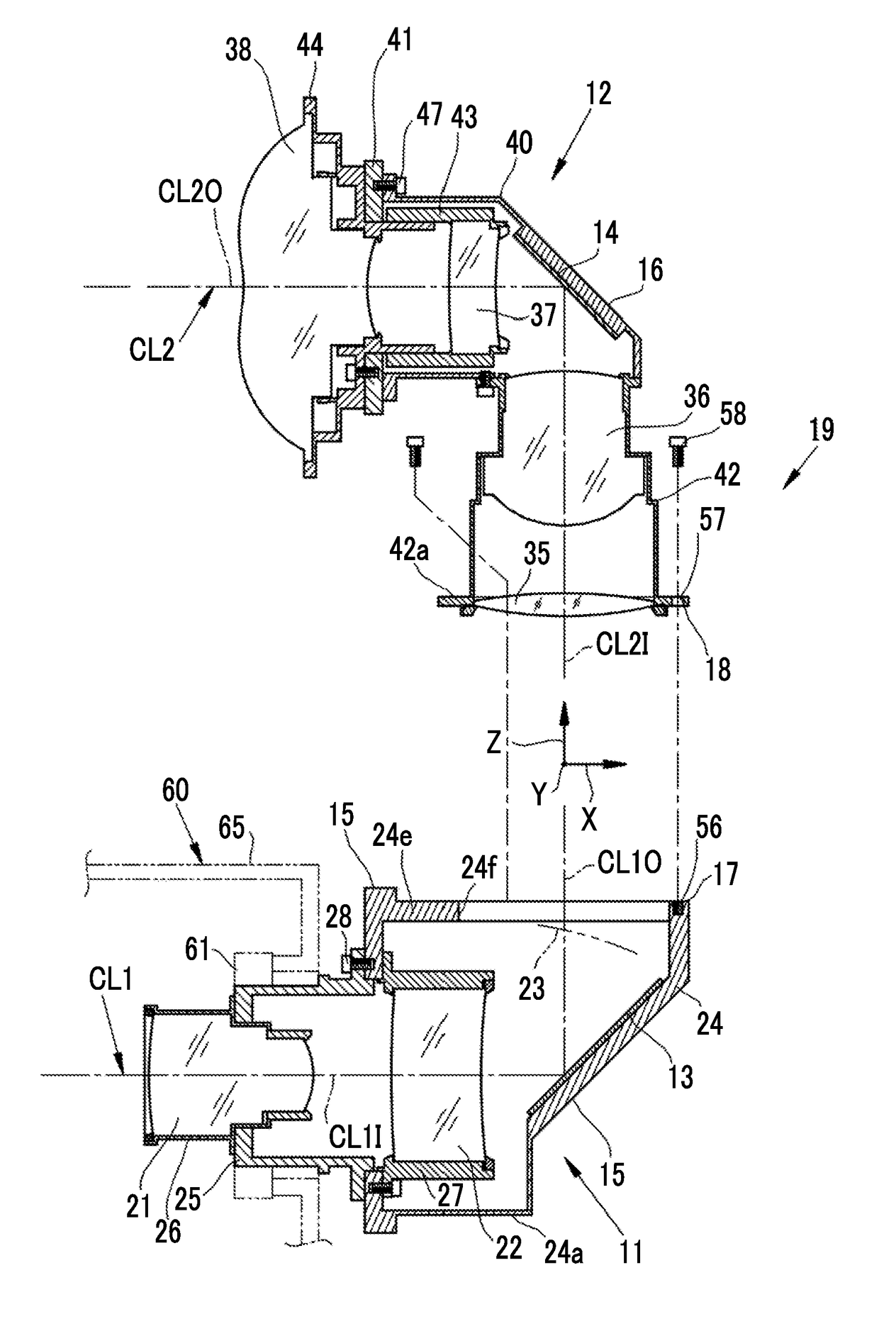
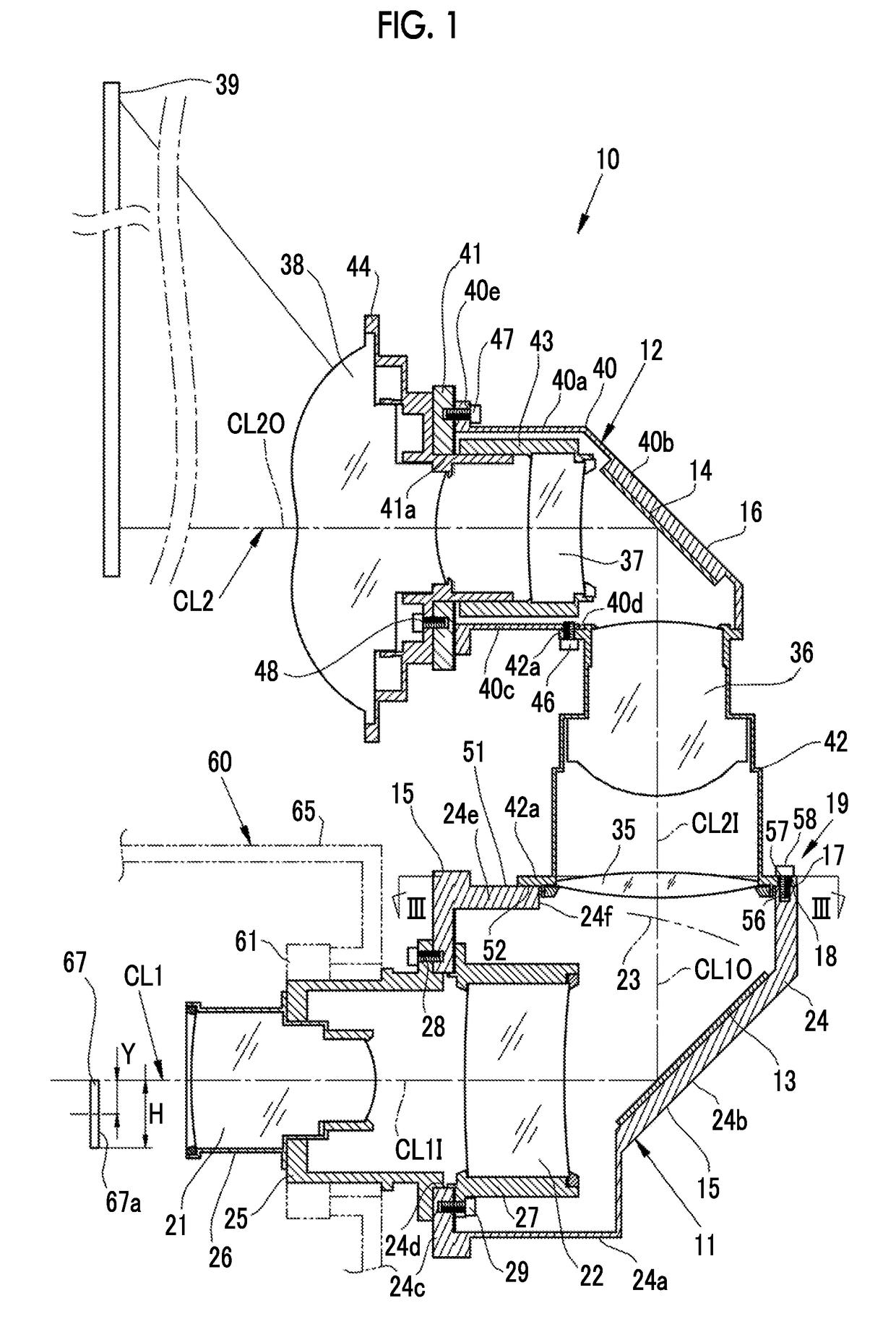
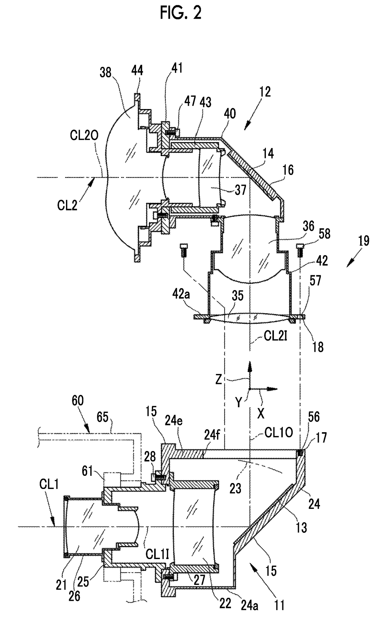
[0028]As shown in FIG. 1, a projection lens 10 of the present embodiment includes a first optical system 11, a second optical system 12, a first mirror 13 as a first optical axis bending member, a second mirror 14 as a second optical axis bending member, a first holding member 15, a second holding member 16, a first junction surface 17, a second junction surface 18, and a junction portion 19.

[0029]The first optical system 11 is composed of a first lens 21 and a second lens 22. The first lens 21 and the second lens 22 are displayed as a single lens for the purpose of simplifying the illustration, but are actually composed of a plurality of lens groups. The first optical system 11 forms an image of an image forming panel 67, as an intermediate image, on an image forming surface 23.

[0030]The first mirror 13 is disposed between the first optical system 11 and the image forming surface 23 of the intermediate image formed by the first optical system 11. The first mirror 13 reflects projec...

second embodiment

[0054]In the first embodiment, using a gap between the screw mounting hole 57 provided in the second holding member 16 and the mounting screw 58 screwed to the first holding member 15, the second holding member 16 is shifted in the XY plane with respect to the first holding member 15, and is rotated around the optical axis (Z-axis). On the other hand, in a second embodiment shown in FIG. 6, an intermediate member 80, a first mounting screw 81, and a second mounting screw 82 are provided to form a junction portion 83. In this junction portion 83, shift adjustment in the XY plane and adjustment around the optical axis are separately performed through the intermediate member 80. Meanwhile, the same configuration members as those in the first embodiment are denoted by the same reference numerals and signs, and thus the repeated description thereof will be omitted below.

[0055]The intermediate member 80 is provided between the first junction surface 17 and the second junction surface 18, ...

third embodiment

[0058]In a third embodiment shown in FIG. 7, an intermediate mount 86 is provided instead of the intermediate member 80 of the second embodiment. The intermediate mount 86 has a well-known mount structure, and junction between the intermediate mount 86 and the second holding member 16 is detachably performed. The intermediate mount 86 includes the same second junction surface 18 as that in the first embodiment on the lower surface. The first holding member 15 includes the first junction surface 17, and the mounting screw 58 is screwed to the screw hole 56, whereby the intermediate mount 86 is fixed to the first holding member 15.

[0059]In a state where the second holding member 16 is mounted to the intermediate mount 86, the first junction surface 17 of the first holding member 15 is closely attached to the second junction surface 18, similarly to the first embodiment. Thereafter, the second holding member 16 is moved relative to the first holding member 15, and a shift in the XY pla...


PUM


Abstract

A first holding member holds a first optical system and a first mirror, and has a first junction surface. A second holding member holds a second optical system and a second mirror, and has a second junction surface. A junction portion is configured such that, in a state where the first junction surface and the second junction surface are aligned with each other, the second holding member is capable of being shifted in a direction of both the junction surfaces and rotated around an optical axis, and makes it possible to perform optical axis alignment. An emission-side optical axis of the first optical system and an incidence-side optical axis of the second optical system are aligned with each other, and thus a U-shaped optical path is formed by the first and second optical systems.

Description

CROSS-REFERENCE TO RELATED APPLICATIONS[0001]This application is a Continuation of PCT International Application No. PCT / JP2016 / 076639 filed on 9 Sep. 2016, which claims priority under 35 U.S.C § 119(a) to Japanese Patent Application No. 2015-192002 filed on 29 Sep. 2015. The above application is hereby expressly incorporated by reference, in its entirety, into the present application.BACKGROUND OF THE INVENTION1. Field of the Invention[0002]The present invention relates to a projection lens and a projector.2. Description of the Related Art[0003]In recent years, projectors having an image forming panel such as a liquid crystal display device or a digital micromirror device (DMD) mounted therein have been in widespread use and have increased in performance. Particularly, with an improvement in the resolution of the image forming panel, there has also been a demand for an improvement in the resolution performance of a projection optical system.[0004]In addition, in consideration of im...

Claims


Application Information

Patent Timeline
Patent Type & Authority Applications(United States)
IPC IPC(8): G03B21/28G02B27/09
CPCG03B21/28G02B27/0955G03B21/147G02B7/021G02B13/16G02B7/02G03B21/00G03B21/14
Inventor KURODA, YASUTO
Owner FUJIFILM CORP
Why Eureka
Try Eureka