Supercharge Your Innovation With Domain-Expert AI Agents!

Gate driver on array driving circuit and LCD device

a technology of array driving circuit and gate driver, which is applied in the direction of static storage, digital storage, instruments, etc., can solve the problems of affecting the reliability of scanning driver, prior art is defective, and needs to be improved and developed, so as to achieve low current leakage and high reliability

Active Publication Date: 2018-08-02
SHENZHEN CHINA STAR OPTOELECTRONICS TECH CO LTD
View PDF2 Cites 13 Cited by
  • Summary
  • Abstract
  • Description
  • Claims
  • Application Information

AI Technical Summary

Benefits of technology

The present disclosure provides a more efficient and reliable scan driving circuit that prevents current leakage. This is achieved by utilizing a pull-up control module with multiple transistors, which improves the reliability of the scanning driver and the display device. This solves the technical problem of conventional scan driving circuits and display devices that are prone to leaking electricity and improves their overall performance.

Problems solved by technology

Further, the variation of an input signal in the pull-up control module may have a big influence on an output signal in the driving module, which affects the reliability of the scanning driver.
Therefore, the prior art is defective and needs to be improved and developed.

Method used


Image

  • Gate driver on array driving circuit and LCD device
  • Gate driver on array driving circuit and LCD device
  • Gate driver on array driving circuit and LCD device

Examples


Embodiment Construction

[0098]The following description of every embodiment with reference to the accompanying drawings is used to exemplify a specific embodiment, which may be carried out in the present invention. Directional terms mentioned in the present invention, such as “top”, “bottom”, “front”, “back”, “left”, “right”, “inside”, “outside”, “side” etc., are only used with reference to the orientation of the accompanying drawings. Therefore, the used directional terms are intended to illustrate, but not to limit, the present invention.

[0099]In the drawings, the components having similar structures are denoted by the same numerals.

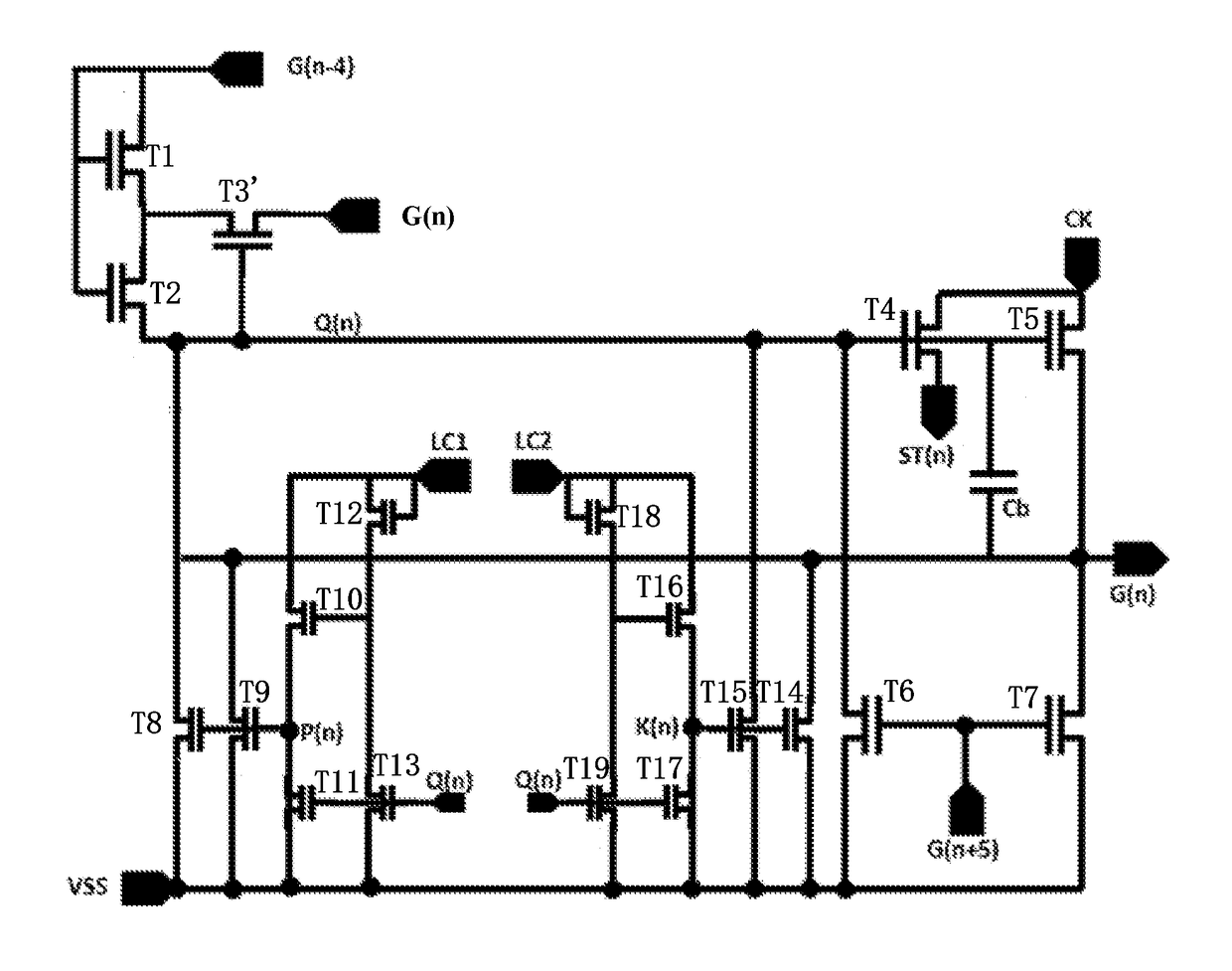
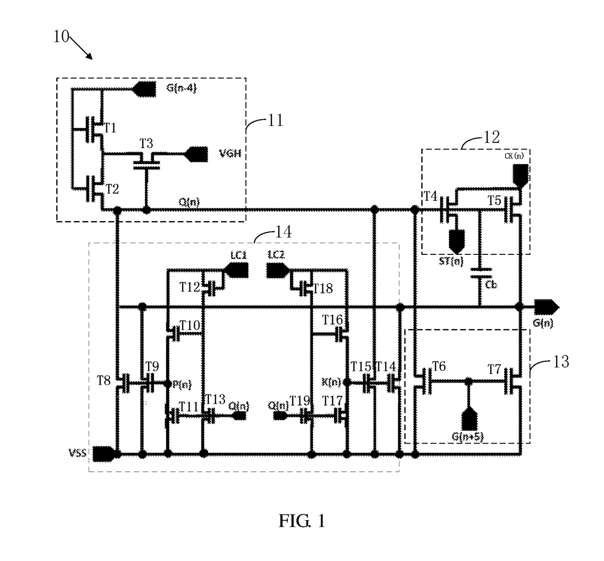
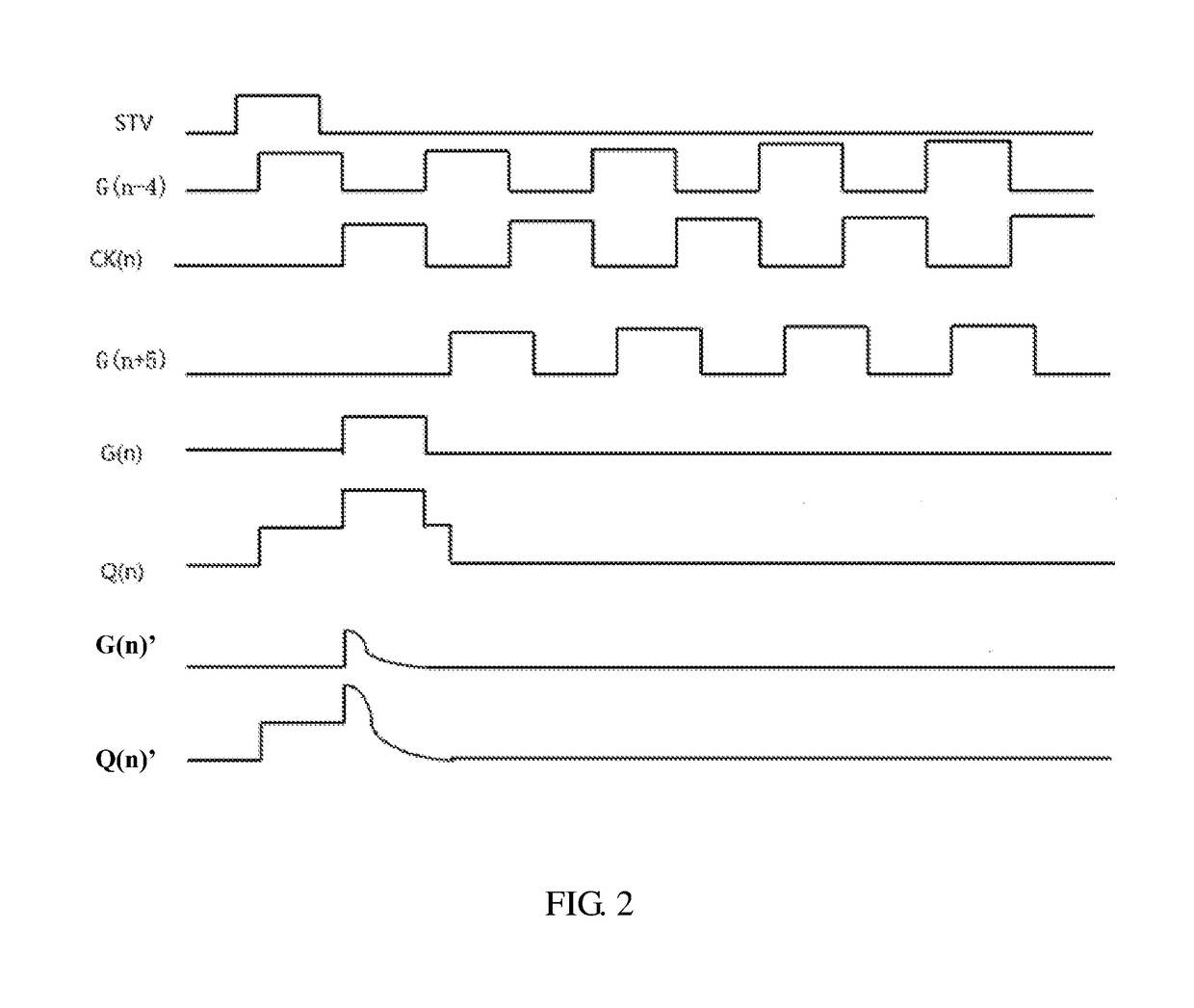
[0100]Please refer to FIG. 1 illustrating a circuit diagram of a scanning driver according to a first embodiment of the present disclosure, and FIG. 2 illustrating waveforms of signals applied on the scanning driver according to the first embodiment of the present disclosure. The scanning driver 10 for driving scan lines row by row, includes cascaded scanning circuits. Each s...


PUM


Abstract

The present disclosure proposes a scanning driver for driving scan lines row by row. The scanning driver includes cascaded scanning circuits. Each scanning circuit includes a pull-up control module, a driving module, a pull-down module, a pull-down holding module, and a constant low voltage supply. The pull-up control module includes a first transistor, a second transistor, and a third transistor.

Description

BACKGROUND1. Field of the Disclosure[0001]The present disclosure relates to the field of liquid crystal displays (LCDs), and more particularly to a gate driver on array (GOA) driving circuit and an LCD device.2. Description of the Prior Art[0002]A gate driver on array circuit (abbreviated as GOA circuit) uses a scan driving circuit that is formed on an array substrate by processing of an array substrate of a traditional thin film transistor-liquid crystal display (TFT-LCD), thus, a driving method for scanning a pixel structure row by row is achieved.[0003]A conventional scan driving circuit includes a plurality of GOA unit. Each GOA unit for driving a scan line includes a pull-up control module, a driving module, a pull-down module, and a pull-down holding module.[0004]The conventional pull-up control module is usually formed by one single transistor. The threshold of a voltage imposed on the transistor tends to become a negative value when the scan driving circuit works in the high...

Claims


Application Information

Patent Timeline
IPC IPC(8): G09G3/36
CPCG09G3/3677G09G2320/0214G09G2310/08G09G2310/0202G09G3/3674G09G2310/0286G11C19/28G11C19/18
Inventor LI, WENYINGCHEN, SHUJHIH
Owner SHENZHEN CHINA STAR OPTOELECTRONICS TECH CO LTD
Features
  • R&D
  • Intellectual Property
  • Life Sciences
  • Materials
  • Tech Scout
  • Unparalleled Data Quality
  • Higher Quality Content
  • 60% Fewer Hallucinations
Learn More