

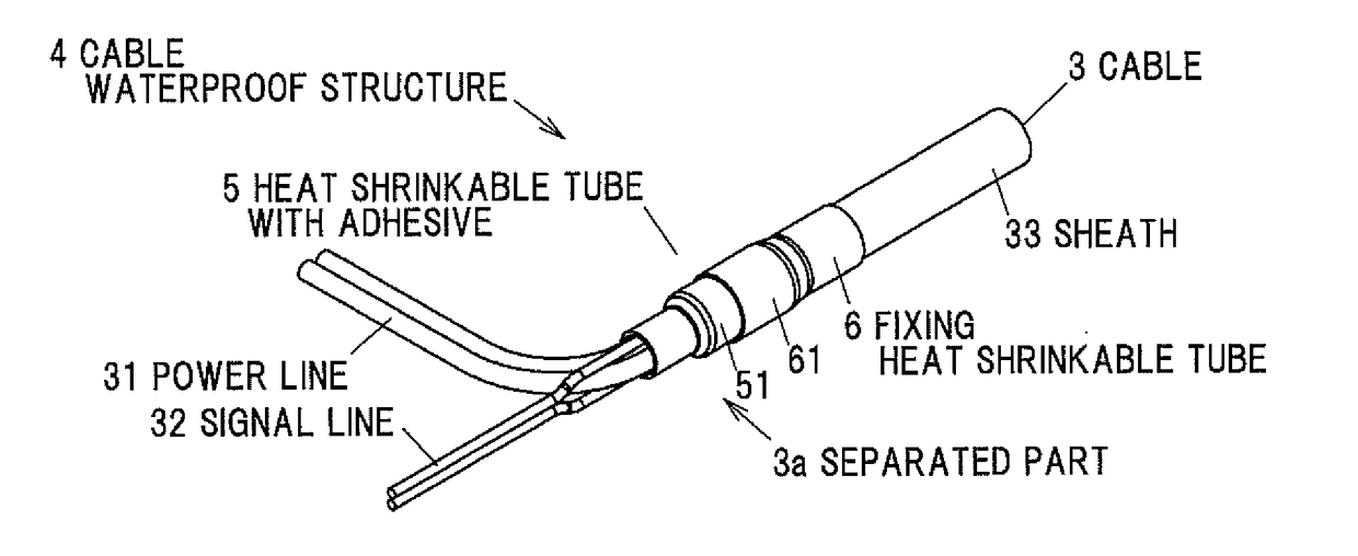
Cable waterproof structure, wire harness, and method of manufacturing wire harness
a technology of waterproof structure and wire harness, which is applied in the direction of insulated conductors, cables, coupling device connections, etc., can solve the problem of not ensuring waterproofness
- Summary
- Abstract
- Description
- Claims
- Application Information
AI Technical Summary
Benefits of technology
Problems solved by technology
Method used
Image

Examples
embodiments
[0044]The embodiment in the invention will be described below in conjunction with the appended drawings.
[0045](Explanation of a Vehicle to Which a Wire Harness is Applied)
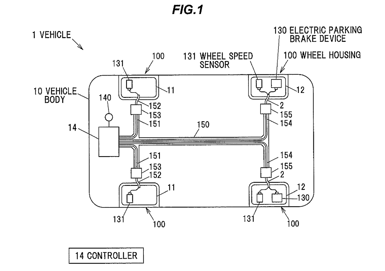
[0046]FIG. 1 is a schematic view showing a structure of vehicle to which a wire harness according to the embodiment is applied.
[0047]A vehicle 1 is provided with four wheel housings 100 in a vehicle body 10. Two front wheels 11 and two rear wheels 12 are arranged in the wheel housings 100 respectively. In the embodiment, the vehicle 1 is a front wheel drive vehicle. The vehicle 1 is driven by subjected to the driving force from a driving source (not shown) provided with an engine or an electrical motor. In other words, the front wheel 11 is a driving wheel and the rear wheel 12 is a driven wheel.
[0048]The vehicle 1 is provided with two EPB devices 130 and a controller 14. The EPB devices 130 are respectively provided on the two rear wheels 12. The EPB devices 130 generate brake force to the rear wheels 12. The cont...
PUM
 Abstract
Description
Claims
Application Information