Substantial energy return shoe with optimal low-impact springs, tuned gear change, and smart knee brace

a technology of low-impact springs and energy-return shoes, which is applied in the direction of low internal friction springs, soles, mechanical equipment, etc., can solve the problems of wasting most of the stored heel impact energy, unable to provide enhanced heel lift and hence substantial energy-return, and difficult to understand energy-return, etc., to achieve less energy-return, less energy-return, and more energy-return

Active Publication Date: 2018-08-09
RRADD INC
View PDF24 Cites 1 Cited by
  • Summary
  • Abstract
  • Description
  • Claims
  • Application Information

AI Technical Summary

Benefits of technology

[0011]Patent application US 2011 / 0138652 of Jun. 16, 2011 by Lucas for Addidas (the famous spring blade shoe) discloses as many blade springs as can be fit in the shoe sole. This sole compresses a minimal amount, ˜¼ inches, which permits many bending blade springs to fit in the footprint. However, the instant invention takes advantage of the fact that it is far better to utilize a minimal number of springs with a thicker sole compression, 1-3 inches in the instant invention, for the following reasons. These few springs (typically two in the instant invention) are more lightweight and easier to manufacture. With regard to the spring blade shoe, the distribution of springs along the entire length of the sole results in less energy return because the rearward springs return their energy even sooner, and, hence, more of that energy is wasted because the coupling between the acceleration of the user's center of mass with said spring action is even worse than if two springs were used (one in the mid section and the other in the heel)—as is most commonly done in conventional shoe designs. These remarks pertain to the use in the instant invention of optimal springs in conventional shoes.
[0012]Krstic, U.S. Pat. No. 7,089,690 of Aug. 15, 2006 discloses an interesting and notable double-sloped conical spring in which the slope changes partway up the cone. In effect, the first cone section coming up from the center plane acts as a spacer so that the force curve bend-over found in Belleville springs occurs early during compression. The only way this snap-through effect can work (with the greater height needed in a shoe sole, i.e., greater than for the relatively small height for Belleville metal springs) is to use a very compliant material such as TPUs (thermoplastic polyurethanes). This is because the perimeter sections of the cone (at the center plane) must circumferentially expand more and more (˜50%) as the relative spring height increases. Unfortunately, this TPU material is an order of magnitude weaker than fiberglass for mirrored arch springs (refer to the discussion of Tables 1-3 of the instant invention). Also, the use of the de facto spacer of the cone section (corresponding to the first cone section with the first slope) compromises the compression ratio of his spring. Finally, the de facto tension element (around the perimeter) is due to the circular configuration—in which case the advantages of the 2D (cylindrical configuration) mirrored springs of the instant invention are not realized. This 2D advantage is that it is possible to precisely choose and vary the shoe total spring stiffness simply by precisely slicing these 2D springs. Furthermore, these 2D springs are much stronger for their weight and for the space used than for the circular configuration.
[0020]Also, improved automatic gear change designs are shown in order to improve the design of the aforesaid enhanced heel-lift shoe designs, herein. These eliminate the need for the anti-toe-sink features of the earlier shoe designs of FIGS. 1-9. The electronic auto gear changer herein is significantly cheaper, and one approach for this design provides precise gear change over the range of gearing—where the gear change is accomplished within one foot step. Of course, the term gear change refers to changing the effective spring strength of the shoe so that there is always full sole compression—just barely without bottoming out. These gear change designs can also be used in conventional shoes without enhanced heel-lift. Since electric power is needed for the electronic auto gear changer, two novel electric shoe chargers are disclosed—one for the enhanced heel-lift shoes with large sole compression travel and another clip-on version for conventional shoes with minimal sole travel. Each of these embodiments has a simple version and an enhanced version, wherein the enhanced version utilizes a gear pulley to increase the turns the generator shaft is spun—by an order of magnitude. The key to making such a gear pulley to work is to manage the rewind of the pulley lines so that there is no slack. A novel method is introduced to accomplish this key capability. These enhanced electric shoe chargers generate far more electric power that those of the prior art, at a reduced price. Thus, the improved designs of the instant patent ensure a futuristic shoe with real energy return via enhanced heel-lift and with minimal foot impact via its constant force curve springs. With the auto gear changer, these optimal features are continuously provided no matter how fast the wearer is walking or running.

Problems solved by technology

This energy return is difficult to understand and very difficult to achieve.
That is, although there are a number of shoe patents that claim to feature energy return by virtue of a whole host of types of conventional springs in their soles, in fact such prior art does not provide enhanced heel-lift and hence substantial energy return.
Thus, most of the stored heel impact energy is wasted because of the resultant and inherent poor coupling of the heel spring action to the acceleration of the user's center of mass upward and forward during heel-lift.
However, that design was very different and impractical; also, it returned some of the foot impact energy at the toe.
That is an admirably simple solution, but unfortunately the design is inherently flawed.
This reduces the height of the parallelogram, which severely reduces the energy return of the shoe as the sole height becomes smaller and smaller.
It is also unacceptable that a wearer must constantly stop and kneel down to make this adjustment.
At the same time, when the impact force is too small for the parallelogram sole to fully compress, there is a severe toe-sink problem in which the wearer's toe flops down and sinks, which is comparable to one's toes sinking when running in the sand.
This is unacceptable, and thus this design neither provides full energy return or a proper toe-off action over most of its range of shoe impact values for a user—in addition to the hassle of requiring the user to kneel down and adjust the shoe by hand every time the running speed changes.
Furthermore, there is no way to correct for this shortcoming in the Freschi design.

Method used


Image

  • Substantial energy return shoe with optimal low-impact springs, tuned gear change, and smart knee brace
  • Substantial energy return shoe with optimal low-impact springs, tuned gear change, and smart knee brace
  • Substantial energy return shoe with optimal low-impact springs, tuned gear change, and smart knee brace

Examples


first embodiment

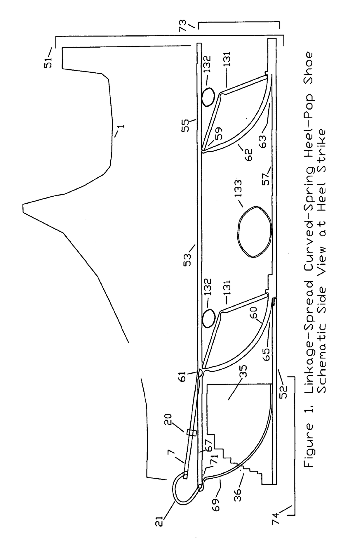
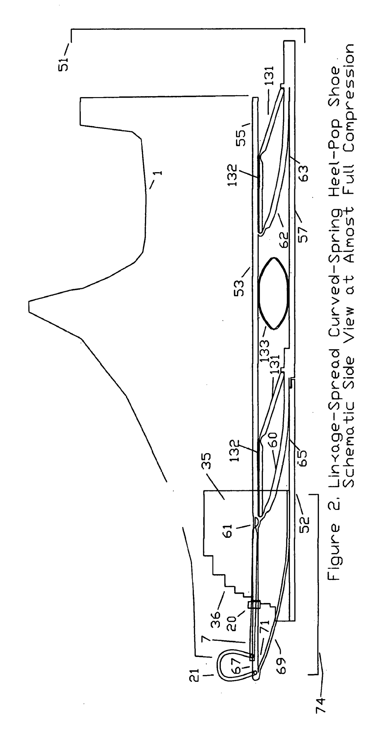
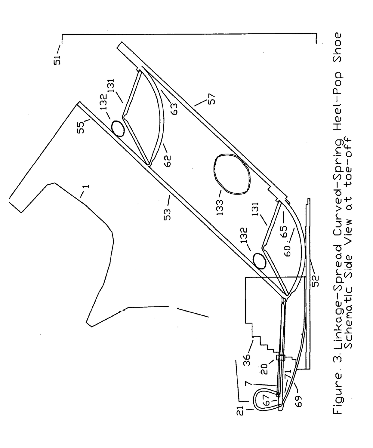
[0076]FIGS. 1, 2, and 3 depict schematic side views at heel strike, mid-stance, and toe-off of the linkage-spread curved-spring heel-pop shoe, which provides enhanced heel lift—which in turn provides substantial energy return. This is the first version of the invention, namely the heel-pop energy return shoe (featuring enhanced heel-lift). The sole compression due to the impact force of running is resisted by a spring system. After the sole is compressed, the runner's toe weight pins down the toe plate of the sole while the combination of the spring system and the sole's parallelogram-like geometry causes the heel section to be lifted upward into the air by an enhanced distance which is of the order of two to three times the compression distance of the heel during the period between heel-strike and mid-stance.

[0077]The basic structure of linkage-spread curved spring heel-pop shoe 51 features linkage-spread curved spring heel-pop sole 73 which comprises the following elements (which ...

second embodiment

[0099]the invention is a class of novel springs, referred to herein as optimal springs in that their force curves are optimized.

These can be complex springs or spring systems. The optimal spring class comprises variations on curved springs and arch springs. These variations are designed to optimize the force curve for footwear and for a number of other applications—where it is advantageous to minimize the maximum force (especially when there is an impact force) on the device structural elements and / or on the user of the device such as a runner. The optimization criterion is to maximize the amount of energy absorbed, namely the area under the force curve for a given maximum force point on that curve. If there are no geometric constraints on the size of the spring, then various conventional springs can be used to achieve force-curve optimized springs, or spring systems. However, the force-curve optimized springs in the instant invention achieve the minimum thickness at full compressio...

fourth embodiment

[0134]FIG. 24 shows schematic side views and a top view of optimal springs in a conventional shoe, which means shoes that do not feature the heel-pop capability for enhanced heel-lift. The use of optimal shoes in conventional shoes is the invention because it can be used in all shoes, thereby providing the health benefits of significantly reduced maximum impact force to the people of the world. Constant thickness shoe 411 comprises shoe upper 1 fixably attached to the top of constant thickness sole 405. Constant thickness shoe 411 comprises shoe upper 1 fixably attached to the top of constant thickness sole 405. Tapered shoe 413 comprises shoe upper 1 fixably attached to the top of tapered thickness sole 407. One or more internal linkage mirrored arch springs 107 can be located in both constant thickness sole 405 and tapered thickness sole 407, e.g. Likewise is true for sideways internal linkage mirrored arch springs 401, which are the same as internal linkage mirrored arch springs ...


PUM


Abstract

A futuristic shoe with true energy return based on enhanced heel-lift, optimized shoe springs (40% reduction in maximum foot impact), practical precise automatic electronic gear changers, novel powerful shoe impact chargers, improved pulley electronic actuators, novel low-impact much stronger springs (featuring the novel use materials such as Kevlar, Spectra Shield, and fiberglass), novel remarkably stronger, more flexible, and tougher structures, and multiple designs for enhanced heel-lift and to prevent excessive toe sink. These designs require linkages and two improved hinges—one with enhanced natural hinges and a second with tied cogged hinges. There is a rotating-arms enhanced optimal spring, which when combined with the tied cogged hinges, results in optimal foldable arrays for deployment in outer space—and which gives a smart energy return knee brace. These novel capabilities promise a wide range of additional applications such as robotics, prosthetics, orthotics, springs, aerospace, automobiles, body armor, and earthquake retrofitting.

Description

BACKGROUND[0001]This instant invention, as disclosed in the instant CIP patent, discloses an array of capabilities for a futuristic optimized shoe invention. It adds alternative designs, extensions, and improvements to the energy return, enhanced heel-lift shoe designs disclosed in its parent USPTO utility patent application Ser. No. 14 / 545,274 filed on Apr. 16, 2015—also of the instant inventor, Rennex. Herein, any reference to this parent application is simply made as the “parent application.” Since the 1980's the holy grail for shoes has been substantial energy return—meaning that a substantial reduction in the metabolic energy cost of running is achieved by an effective coupling of the sole stored impact energy to lift the center of mass of the runner upward and forward during take-off. Simply putting springs anywhere in the sole provides only a few percent energy cost reduction—no matter how high the coefficient of restitution is for these simple springs. The issues of heel-toe...

Claims


Application Information

Patent Timeline
Patent Type & Authority Applications(United States)
IPC IPC(8): A43B13/18A43B13/14A43B3/00F16F3/087F16F3/02
CPCA43B13/184A43B13/141F16F3/02A43B13/145A43B13/183A43B3/0005F16F3/0876Y10S901/01A43B3/38A43B3/34
Inventor RENNEX, BRIAN
Owner RRADD INC
Why Eureka
Try Eureka