Method for controlling brakes in a trailer vehicle

US20180222463A1Active Publication Date: 2018-08-09ZF CV SYST EURO BV

Image

  • Method for controlling brakes in a trailer vehicle
  • Method for controlling brakes in a trailer vehicle
  • Method for controlling brakes in a trailer vehicle

Examples


Embodiment Construction

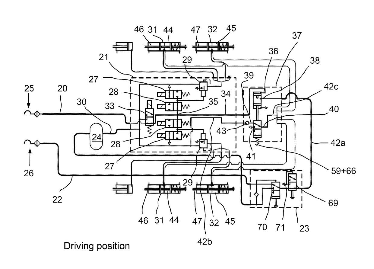
[0039]With reference to the specific embodiment of the Figures, wherein like numerals generally indicate like parts throughout the several views, FIG. 4 shows a pneumatic brake system for a trailer vehicle. A control pressure line 20 leads to a trailer brake module 21. A supply pressure line 22 leads to a parking release valve 23 and from this further via a reservoir container 24 to the trailer brake module 21. According to certain legal regulations, the control pressure line 20 comprises a yellow coupling head 25 for a control port and the supply pressure line 22 comprises a red coupling head 26 for a supply port.

[0040]The trailer brake module 21 may be constructed in a known way, namely with two solenoid valves 27, 28 and one relay valve 29 on each side of the vehicle. The delivery of the control pressure to the relay valves 29 is controlled via the solenoid valves 27, 28. The latter are connected at the same time to the reservoir container pressure from the reservoir container 24...


PUM


Abstract

Disclosed is a method for controlling brakes in a trailer vehicle comprising a pneumatic brake system, service brakes and an electronic brake system with anti-lock control, wherein at least one axle of the trailer vehicle is fitted with spring-loaded brakes and revolution rate sensors. The method comprises: monitoring with the electronic brake system whether there is a braking demand, monitoring with the electronic brake system whether at least one wheel of at least one axle is locking up, and if there is no braking demand and at least one wheel of the at least one axle is locked while traveling, controlling the pneumatic braking system with the electronic brake system to pressurize the spring-loaded brakes and to brake the trailer vehicle by the service brakes automatically and with anti-lock control. A valve arrangement is also disclosed.

Description

CROSS-REFERENCE TO RELATED APPLICATIONS[0001]This application is the National Stage of International Application No. PCT / EP2016 / 000920, filed on 4 Jun. 2016, which claims priority to and all advantages of German Patent Application No. 10 2015 007 384.2, filed on 10 Jun. 2015, the content of which is hereby incorporated by reference.FIELD OF THE INVENTION[0002]The invention generally relates to a method for controlling brakes in a trailer vehicle with a pneumatic brake system, service brakes and an electronic brake system with anti-lock control, wherein at least one axle of the trailer vehicle is fitted with spring-loaded brakes and revolution rate sensors, and wherein the pneumatic brake system comprises a reservoir container with a reservoir container pressure.BACKGROUND OF THE INVENTION[0003]Modern utility vehicles—towing vehicles and trailer vehicles—are equipped with a pneumatic brake system, which is at a higher level than an electronic brake system. Moreover, an anti-lock cont...

Claims


Application Information

Patent Timeline
09 Aug 2018
Publication
US20180222463A1
IPC
B60T8/32; B60T13/66; B60T13/38; B60T13/68
CPC
B60T13/662; B60T13/385; B60T13/683; B60T8/327; B60T8/1708; B60T8/323; B60T13/38; B60T13/66
Inventors
RISSE, RAINER; SIEKER, ARMIN