
Small pulsation thin type air compressor

A technology of air compressor and compression mechanism, which is applied in the direction of machine/engine, liquid fuel engine, rotary piston type/oscillating piston type pump components, etc., which can solve the problem of reducing the service life of the motor, the impact of motor power and speed output, and no intersection and other problems to achieve the effect of solving stuck and protecting the motor

Active Publication Date: 2016-08-17
海门市知舟工业设计有限公司
View PDF5 Cites 0 Cited by
  • Summary
  • Abstract
  • Description
  • Claims
  • Application Information

AI Technical Summary

Problems solved by technology

[0002] At present, the air compressor is composed of a motor, a compressor and an air storage tank. The compressor is installed on the shaft of the motor. The space occupied by the periphery of the compressor does not overlap with the space occupied by the periphery of the motor. The total length of the direction must be greater than the sum of the length of the motor and the length of the compressor. In addition to the space of the air storage tank, the overall installation will occupy a large part of the space, which will have adverse effects on use, transportation and storage.
In addition, the compressed air process is a reciprocating cycle process. In each cycle process, there are two processes: the beginning of air compression and the end of air compression. The air compressibility of the two processes is different, which will affect the power and speed of the motor. The output produces impact, which will reduce the service life of the motor

Method used


Image

  • Small pulsation thin type air compressor
  • Small pulsation thin type air compressor
  • Small pulsation thin type air compressor

Examples


Embodiment Construction

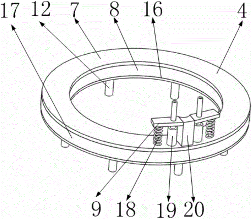
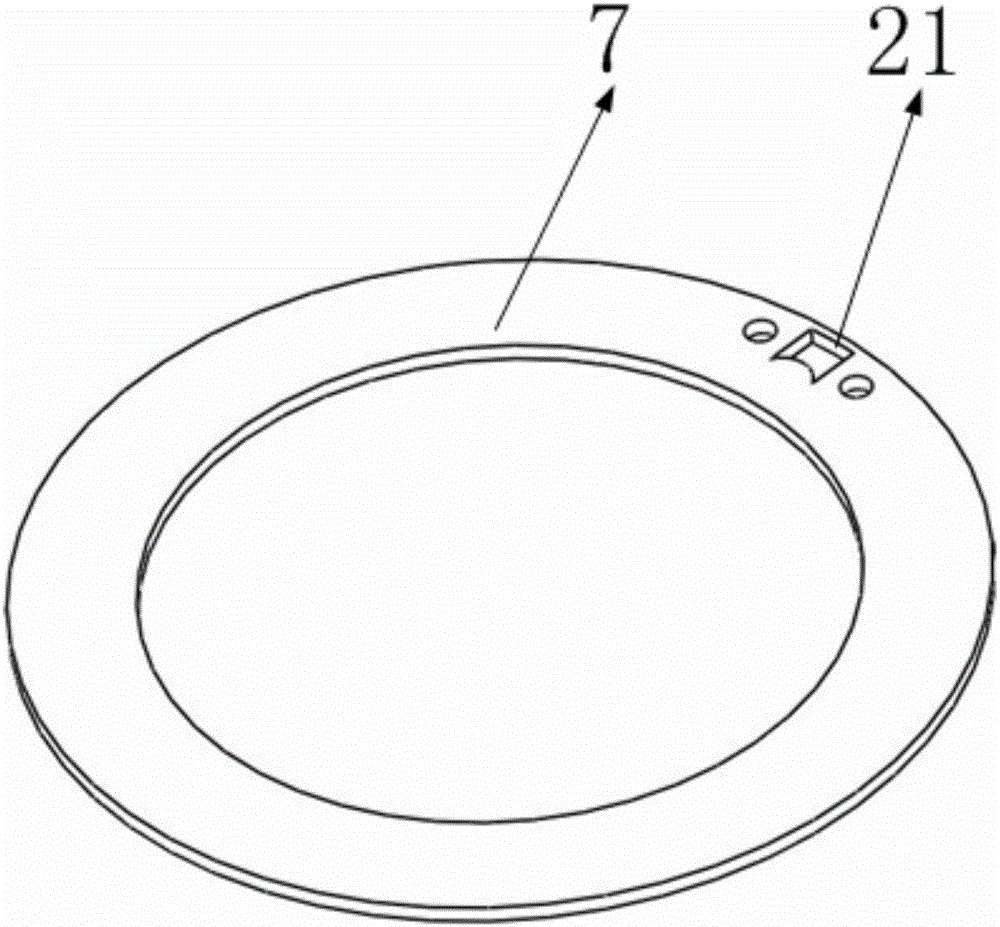
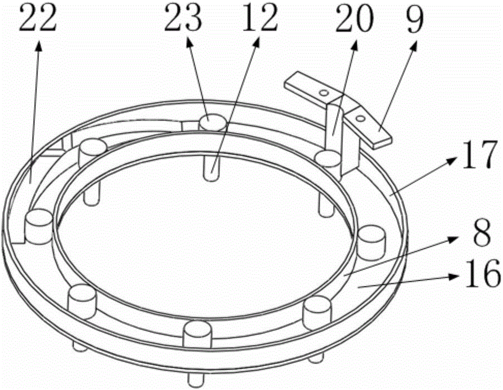
[0028] Such as Figure 7 , 8 As shown, a small pulsation thin air compressor is characterized in that it includes a support column, a base, a motor, a compression mechanism, a first internal tooth, a first external tooth, a second internal tooth, a second external tooth, a first Three inner teeth, third outer teeth, first center teeth, second center teeth, third center teeth, motor shaft, among which Figure 7 As shown, the compression mechanism is installed on the base through three support columns uniformly fixed in the circumferential direction; the motor is installed in the center of the compression mechanism, and the thickness of the motor is the same as that of the compression mechanism; Figure 11 As shown, the diameters of the first central tooth, the second central tooth, and the third central tooth decrease in order, and they are installed on the motor shaft of the motor in sequence, and the first central tooth is closest to the end face of the motor; Figure 9 , ...


PUM


Abstract

The invention belongs to the technical field of air compressors, and particularly relates to a small pulsation thin type air compressor. The small pulsation thin type air compressor comprises supporting columns, a base, first rotating shafts, compression blocks, a compression mechanism, a motor, center gears, internal teeth, external teeth and the like. The compression mechanism is mounted on the base through the supporting columns; the motor which is mounted at the center of the compression mechanism drives the eight first rotating shafts to rotate through the three center gears of different diameters via the eight internal teeth and the eight external teeth; and the first rotating shafts have three rotating speeds due to the different diameters of the three center gears. When compression is started, the rotating speeds of the first rotating shafts are set to be high so that air can be pressurized quickly; and when compression is ended, the rotating speeds of the first rotating shafts are set to be low so that the motor can operate stably with small pulsation in the whole compression process. In addition, the mode that the motor is mounted in a ring of the ring-shaped compressor is adopted, so that the size of equipment is greatly reduced, the purpose of convenient usage, storage and transportation is achieved, and a good application effect is achieved.

Description

Technical field [0001] The invention belongs to the technical field of air compressors, in particular to a small-pulse thin air compressor. Background technique [0002] At present, the air compressor is composed of a motor, a compressor and an air storage tank. The compressor is installed on the shaft of the motor. The space occupied by the periphery of the compressor does not overlap with the space occupied by the periphery of the motor. The total length of the direction must be greater than the sum of the length of the motor and the length of the compressor, plus the space of the air storage tank, the overall installation will take up a large part of the space, which will have an adverse effect on use, transportation, and storage. In addition, the compressed air process is a reciprocating cycle process. In each cycle process, there are two processes: the beginning of air compression and the end of air compression. The air compressibility of the two processes is different,...

Claims


Application Information

Patent Timeline
Patent Type & Authority Applications(China)
IPC IPC(8): F04C23/02F04C18/32F04C29/00
CPCF04C18/32F04C23/02F04C29/005
Inventor 朱敏
Owner 海门市知舟工业设计有限公司
Learn More