
Power source unit body for ejection, aircraft carrier gas steam ejector and ejection method

A technology of gas steam and power source, applied in the direction of cartridge ammunition, launching/dragging transmission device, ammunition, etc., it can solve the problems of large pressure loss, large forward resistance of piston assembly, impossibility of catapult, etc.

Active Publication Date: 2015-09-09
任明琪
View PDF6 Cites 0 Cited by
  • Summary
  • Abstract
  • Description
  • Claims
  • Application Information

AI Technical Summary

Problems solved by technology

[0028] The inventor thinks that, from the perspective of the ejection performance required by kinematics and dynamics alone, the pressure of the steam that has just left the ejection valve and enters the open cylinder working chamber to push the rear end of the piston assembly should increase as the ejection speed increases, but now The steam pressure in the gas storage tank of the state-of-the-art technology remains basically constant, while at the end of the ejection the pressure loss is large when the steam passes through the ejection valve, and the pressure of the steam entering the working chamber of the open cylinder is greatly reduced, that is, the real push of the piston assembly The forward steam pressure is very low, and the resistance of the piston assembly to advance becomes larger, so it is impossible for the catapult with this structure to achieve uniform accelerated ejection
The inventor believes that this is mainly because the steam catapult and the main drive share a power source, and the steam consumption of the steam catapult is large, the steam consumed by the ejection cannot be replenished in time, and the gas storage tank does not have The function of quickly increasing the steam pressure cannot rapidly and greatly increase the steam pressure entering the working chamber of the open cylinder during the ejection process.

Method used


Image

  • Power source unit body for ejection, aircraft carrier gas steam ejector and ejection method
  • Power source unit body for ejection, aircraft carrier gas steam ejector and ejection method
  • Power source unit body for ejection, aircraft carrier gas steam ejector and ejection method

Examples


Embodiment Construction

[0049] Embodiments of the present invention will be described in detail below with reference to the drawings.

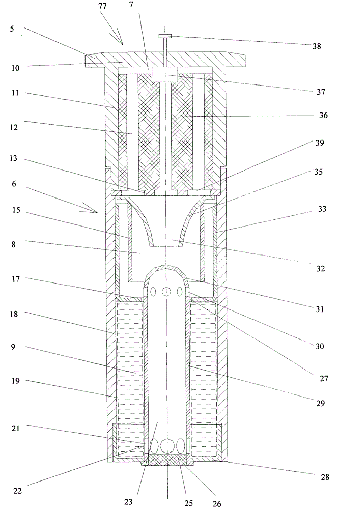
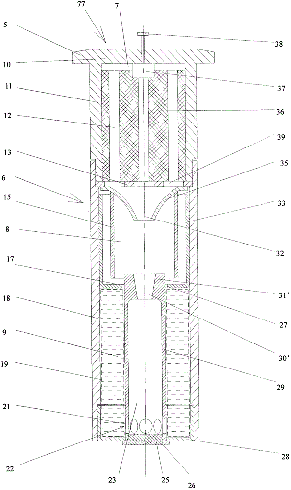
[0050] figure 1 It is the structural representation of gas steam bomb 77 of the present invention. Such as figure 1 As shown, the cartridge case 6 of the gas steam bomb 77 includes a cylinder bottom 11 and a cylinder portion 18, and one end of the cylinder bottom 11 and the cylinder portion 18 is connected as a whole by a screw thread (also can be other ways), and the cylinder bottom 11 has an ejection shell. The bottom edge 5 used is provided with a porous fixed frame 13 inside the cartridge case 6, and the fixed frame 13 is fixed with gunpowder 36 (or called solid propellant), between the gunpowder 36 and the bottom 10 of the bottom 11 of the barrel. An igniter 37 is provided, and an igniter control device 38 is arranged on the outside of the cylinder bottom 10 at a position capable of firing from the outside, and is connected to the igniter 37 through the cylind...


PUM


Abstract

A power source unit body for catapulting. The power source unit body for catapulting (77) comprises a high-pressure chamber (7), a flow splitting chamber (8) and a cooling water chamber (9). High-temperature high-pressure fuel gas generated through burning of gunpowder (36) enters the flow splitting chamber, a part of the fuel gas enters a vertical pipe (29) from a fuel gas inlet, and another part of the fuel gas squeezes a water bag (19) in the cooling water chamber, so that cooling water in the water bag is sprayed into the vertical pipe from a cooling water nozzle, and is mixed with high-temperature high-pressure fuel gas to generate steam, and the steam and the gunpowder fuel gas are formed into mixed gas. In the power unit body for catapulting, gunpowder is placed in a cartridge case (6), and when it is required to release energy, high-pressure gas may be released through percussion of the power unit body, thereby implementing catapulting of a shipboard aircraft. Also, an aircraft carrier gas-steam catapult and a catapulting method for implementing catapulting of a shipboard aircraft by use of the power unit body.

Description

technical field [0001] The invention relates to a power source unit body for ejection, an aircraft carrier gas steam catapult and an ejection method, in particular to a power source unit body for ejection and a power source unit for ejection that generate steam by heating cooling water with high-temperature and high-pressure gas generated by the combustion of gunpowder A gas-steam catapult and an ejection method thereof are provided as a power source to assist carrier aircraft on an aircraft carrier to take off. Background technique [0002] Due to the multiple functions of the aircraft and the high comprehensive combat effectiveness, since the Wright brothers invented the aircraft, people have tried to make the aircraft take off and land on warships. There are currently three main ways for fixed-wing aircraft to take off from an aircraft carrier: vertical / short take-off and landing aircraft directly take off from the flight deck; ski jump takeoff; and catapult takeoff. [...

Claims


Application Information

Patent Timeline
Patent Type & Authority Patents(China)
IPC IPC(8): B64F1/06
CPCB64F1/06F42B5/145F42B3/04Y02T50/82Y02T50/80
Inventor 任明琪闫飞宇吕磊
Owner 任明琪
Learn More