Loop soaking plate

A vapor chamber and loop technology, applied in the field of heat dissipation of electronic components, can solve the problems of aggravating the heat load of the chip, increasing the burning of electronic components, low heat transfer efficiency, etc., to alleviate the heat load problem, speed up replenishment and evaporation , improve the effect of evaporation

Inactive Publication Date: 2017-07-14
GUANGZHOU HUAZUAN ELECTRONICS TECH
View PDF9 Cites 14 Cited by
  • Summary
  • Abstract
  • Description
  • Claims
  • Application Information

AI Technical Summary

Problems solved by technology

However, when faced with the heat dissipation problem of high-power chips with hundreds of wattages, the cold heat dissipation equipment formed by setting aluminum fins above the vapor chamber cover or only changing the internal structure of the vapor chamber can no longer meet the corresponding requirements. Heat dissipation requirements, the extremely high heat flux will cause a large amount of heat to still gather in the center and extension of the hot plate, and the low heat transfer efficiency will further increase the heat load of the chip and increase the risk of electronic components being burned

Method used


Image

  • Loop soaking plate
  • Loop soaking plate
  • Loop soaking plate

Examples


Embodiment 1

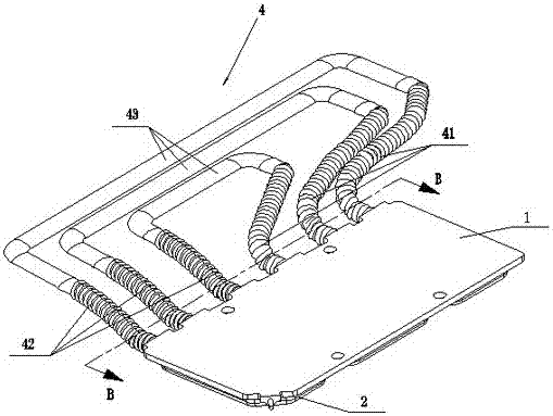
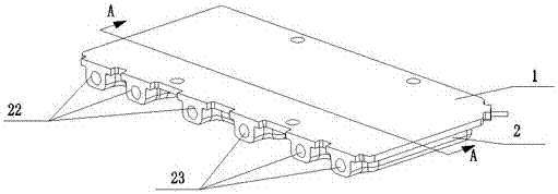
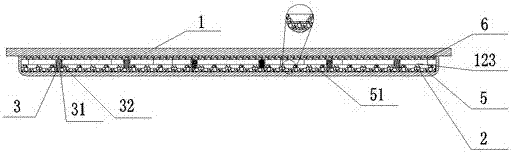
[0032] see Figure 1-Figure 5 As shown, it is the three-dimensional structure diagram and the A-A and B-B cross-sectional views of the first embodiment of the loop vapor chamber structure of the present invention. As shown in the figure, the loop vapor chamber includes an upper cover plate 1, a bottom plate 2, The support structure 3, the capillary structure layer and the loop component 4 that can accommodate the flow of working fluid. In this embodiment, the liquid working medium is preferably distilled water. Wherein, the capillary structure layer includes a first capillary structure layer 5, a second capillary structure layer 6 and a third capillary structure layer 7. In order to increase the capillary adsorption force, a plurality of slopes are arranged on the first capillary structure layer 5. groove 51, the upper cover plate 1 is welded together with the bottom plate 2 provided with a concave square chamber to form a sealed vacuum plate shell 12, the plate shell 12 is f...

Embodiment 2

[0041] see Figure 6 and Figure 7 As shown, it is the three-dimensional structure diagram and the C-C sectional view of the second embodiment using the new loop vapor chamber. As shown in the figure, part of the structure of this embodiment is the same as that of the aforementioned first embodiment, so it will not be repeated here To repeat, the difference between this embodiment and the aforementioned first embodiment is that the liquid pipe body 42 in the loop assembly in this embodiment is a helical copper tube with a fourth capillary structure layer 422 in its inner cavity. The copper powder with a particle size of 80-150 mesh used in the fourth capillary structure layer 422 is sintered. The liquid section pipe body 42 is in a spiral shape, and the pipe diameter of the liquid section pipe body 42 near the condensing unit 43 is smaller than that of the liquid section pipe body 42 near the bottom plate 2, which is favorable for forward circulation flow. Since the inner ca...

Embodiment 3

[0043] see Figure 8 As shown, it is the three-dimensional structure diagram of the third embodiment using the new loop vapor chamber. As shown in the figure, part of the structure of this embodiment is the same as that of the first embodiment, so it will not be repeated here. However, The difference between this embodiment and the aforementioned first embodiment is that both the steam section pipe body 41 and the liquid section pipe body 42 in the loop assembly in this embodiment are made of copper pipes. The copper tube with a simple structure can reduce the manufacturing process of the vapor chamber in this loop, and has little influence on the heat dissipation performance of the overall device.

[0044] The working principle of the present invention is: when the chip with high heat flux density is closely attached to the bottom surface of the bottom plate 2, the heat is transferred to the first capillary structure layer 5 through the bottom plate 2, and the liquid working ...


PUM


Abstract

The invention discloses a loop soaking plate, and aims to provide the loop soaking plate with simple structure, low cost and higher generality and particularly suitable for high-heat-flux places. The loop soaking plate comprises a cover plate and a baseplate; the cover plate is fixed on the baseplate; a closed vacuum plate shell is formed between the cover plate and the baseplate; a first capillary structure layer and a second capillary structure layer are arranged in the plate shell; an evaporation cavity is formed between the first capillary structure layer and the second capillary structure layer; multiple support structures are vertically arranged between the first capillary structure layer and the second capillary structure layer; the first capillary structure layer is permeated with a liquid-state working medium; the plate shell is provided with at least one loop module for accommodating the working medium to flow; and the loop module communicates with the evaporation cavity.

Description

technical field [0001] The invention relates to heat dissipation of electronic components, in particular to a loop soaking plate used for heat dissipation of integrated chips. Background technique [0002] The development of intelligent equipment and the Internet of Things has accelerated the performance requirements of chips. Highly integrated chips will be accompanied by high heat flux density, which seriously affects the response rate of equipment. However, the single-phase cooling technology that only adds fans and cooling fins on the chip can no longer meet the problem of high heat flux density of the existing chip. Compared with traditional air cooling technology and liquid cooling technology, phase change heat transfer technology is one of the most extensively researched thermal control technologies at present, especially with the help of vapor chamber technology of evaporation and condensation of liquid working fluid, the composite heat dissipation model composed of ...

Claims


Application Information

Patent Timeline
Patent Type & Authority Applications(China)
IPC IPC(8): F28D15/04
CPCF28D15/04F28D15/043F28D15/046
Inventor 陈平高明智
Owner GUANGZHOU HUAZUAN ELECTRONICS TECH
Why Eureka
Try Eureka