Vane pump

a technology of vane pump and working fluid, which is applied in the direction of rotary/oscillating piston pump components, machines/engines, liquid fuel engines, etc., can solve the problems of unsatisfactory effect, cavitation or noise, and the inability to smoothly suction the working fluid into the rotary chamber rs, so as to minimize damage to the vane or occurrence, smooth drawing of working fluid, and excellent flow rate and volumetric efficiency

Inactive Publication Date: 2018-08-09
MEIWA IND CO LTD
View PDF5 Cites 0 Cited by
  • Summary
  • Abstract
  • Description
  • Claims
  • Application Information

AI Technical Summary

Benefits of technology

[0020]The present invention described above relates to a vane pump has a merit of being capable of smoothly drawing a working fluid drawn into a rotary chamber while minimizing damage to a vane or occurrence of noise, having an excellent performance in terms of flow rate and volumetric efficiency, and being capable of effectively reducing inner cavitation.

Problems solved by technology

However, the conventional outer cam ring 20 had a limitation in that the working fluid suctioned into the rotary chamber RS could not be smoothly suctioned due to suction resistance of the working fluid suctioned, and thus, cavitation or noise occurred.
However, also in the case of the vane pump, which was for continuously variable transmissions and was disclosed in the Koran Laid-open Patent Publication, a circular through hole b is simply formed in the cam ring 80 to solve the above-mentioned limitation, but the effect thereof was unsatisfactory.
In addition, stepped parts a were formed in the upper and lower portions of the cam ring 80 so as to smoothly suction the working fluid, but shaking of the vanes was caused due to the stepped parts a, and therefore, a smooth pressure-transport could not be carried out, and further, the stepped parts a caused damage to the vanes and noise.

Method used


Image

  • Vane pump
  • Vane pump
  • Vane pump

Examples


first embodiment

[0046]First, referring to FIG. 6, an outer cam ring 100 of the first embodiment will be described.

[0047]The outer cam ring 100 of the first embodiment has, on a portion thereof corresponding to the side to which the working fluid is introduced, a rectangular through slit 100h which extends in the circumferential direction thereof.

[0048]Specifically, the upper end part 111 of the outer cam ring 100 has one portion in which the rectangular through slit 100h is formed, and which is formed in the same height as the remaining portion thereof, and the lower end part 113 of the outer cam ring 100 has one portion, in which the rectangular through slit 100h is formed, and which is formed in the same height as the remaining portion thereof. That is, the outer cam ring 100 is formed such that the upper and lower portions thereof are formed to be flat overall.

[0049]Meanwhile, the upper end part 111 of the outer cam ring 100 having the through slit 100h formed therein and the lower end part 113 ...

second embodiment

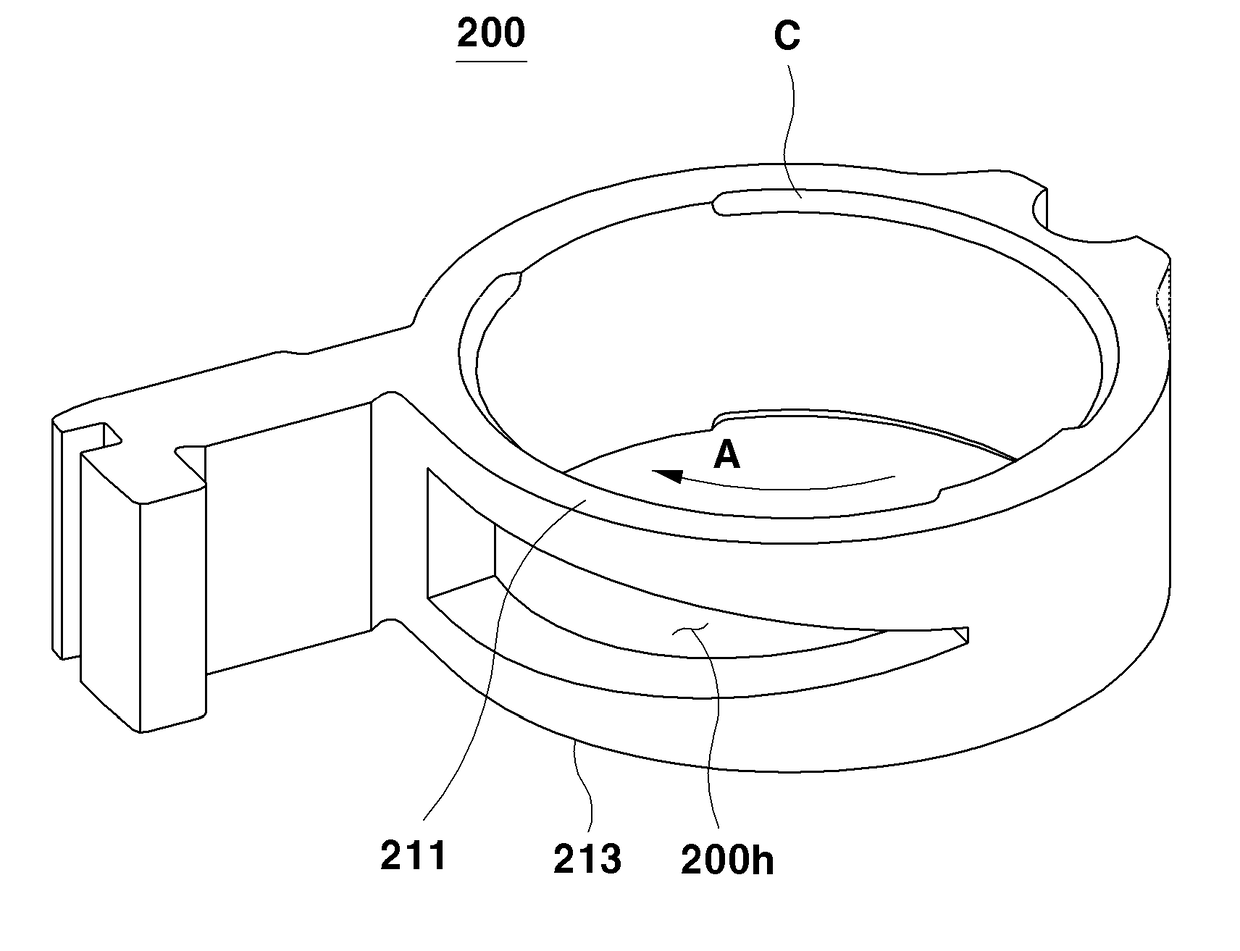
[0052]Next, referring to FIG. 7, an outer cam ring 200 of the second embodiment will be described.

[0053]The outer cam ring 200 of the second embodiment has, on the corresponding portion of the outer cam ring 200 corresponding to the side where the working fluid is introduced into a rotary chamber, a through slit 200h which has a shape of an approximate isosceles triangle and extends in the circumferential direction of the outer cam ring 200. That is, an upper end part 211 and a lower end part 213 of the outer cam ring 100 respectively have portions which have the through slit 200h formed therein and are formed to be vertically symmetrical to each other.

[0054]Specifically, the upper end part 211 and the lower end part 213 of the outer cam ring 200 have portions which have the through slit with an isosceles triangle shape 200h formed therein, the portions being formed to have heights which gradually increase in the opposite direction to a moving direction A of he working fluid, and co...


PUM


Abstract

A vane pump is configured to discharge a working fluid introduced into one side of a rotary chamber formed between an outer cam ring and a rotor to the other side of the rotary chamber, wherein a through slit extending in a circumferential direction of the outer cam ring is formed in a corresponding portion of the outer cam ring corresponding to the side to which the working fluid is introduced into the rotary chamber.

Description

TECHNICAL FIELD[0001]The present invention relates to a vane pump which is capable of smoothly suctioning a working fluid suctioned into a rotary chamber while minimizing damage to a vane or occurrence of noise, exhibits an excellent performance in terms of flow rate and volumetric efficiency, and is capable of effectively reducing inner cavitation.BACKGROUND ART[0002]Pumps function to supply a working fluid to each portion of an engine to smoothly operating the engine, are configured to apply a pressure to the working fluid using mechanical energy of the engine such as a motor, an internal combustion engine, or a steam engine and then circulate the working fluid to each portion of the engine, and are classified into vane-type pumps and piston-type pumps.[0003]Meanwhile, pumps include constant-volume pumps having constant discharge quantities under load variation and variable-capacity pumps having varying discharge quantities according to load variation.[0004]As illustrated in FIGS....

Claims


Application Information

Patent Timeline
Patent Type & Authority Applications(United States)
IPC IPC(8): F04C15/00F04C2/344
CPCF04C15/0042F04C2/344F04C2240/10F04C2/3441F04C15/06F01C21/106F04C14/22F04C14/223F04C14/226F04C2240/802
Inventor JUNG, HYUNEUKIM, SANGWOO
Owner MEIWA IND CO LTD
Why Eureka
Try Eureka