Radar assembly with ultra wide band waveguide to substrate integrated waveguide transition

Active Publication Date: 2018-08-09
APTIV TECH LTD
View PDF0 Cites 8 Cited by
  • Summary
  • Abstract
  • Description
  • Claims
  • Application Information

AI Technical Summary

Benefits of technology

[0003]Described herein is a wideband transition that is formed using standard printed circuit board (PCB) processes, so is able to avoid using expensive waveguide flanges or metal structures. The non-limiting example described herein provides a transition between a Rectangular Waveguide (RWG) to a Substrate Integ

Problems solved by technology

Known transitions with sufficient bandwidths include undesirably expensive wav

Method used


Image

  • Radar assembly with ultra wide band waveguide to substrate integrated waveguide transition
  • Radar assembly with ultra wide band waveguide to substrate integrated waveguide transition
  • Radar assembly with ultra wide band waveguide to substrate integrated waveguide transition

Examples


Example

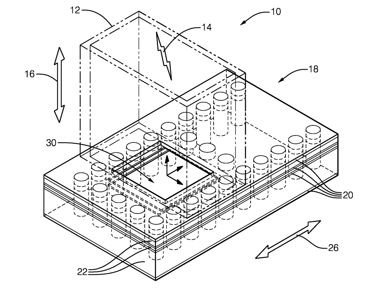
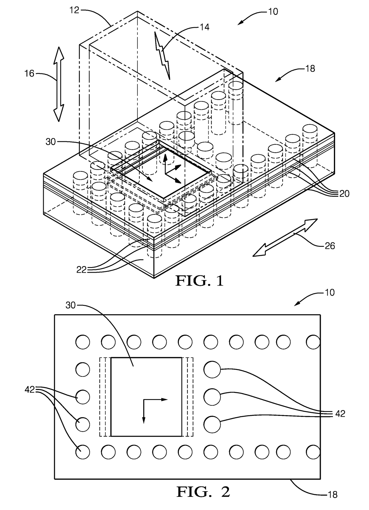
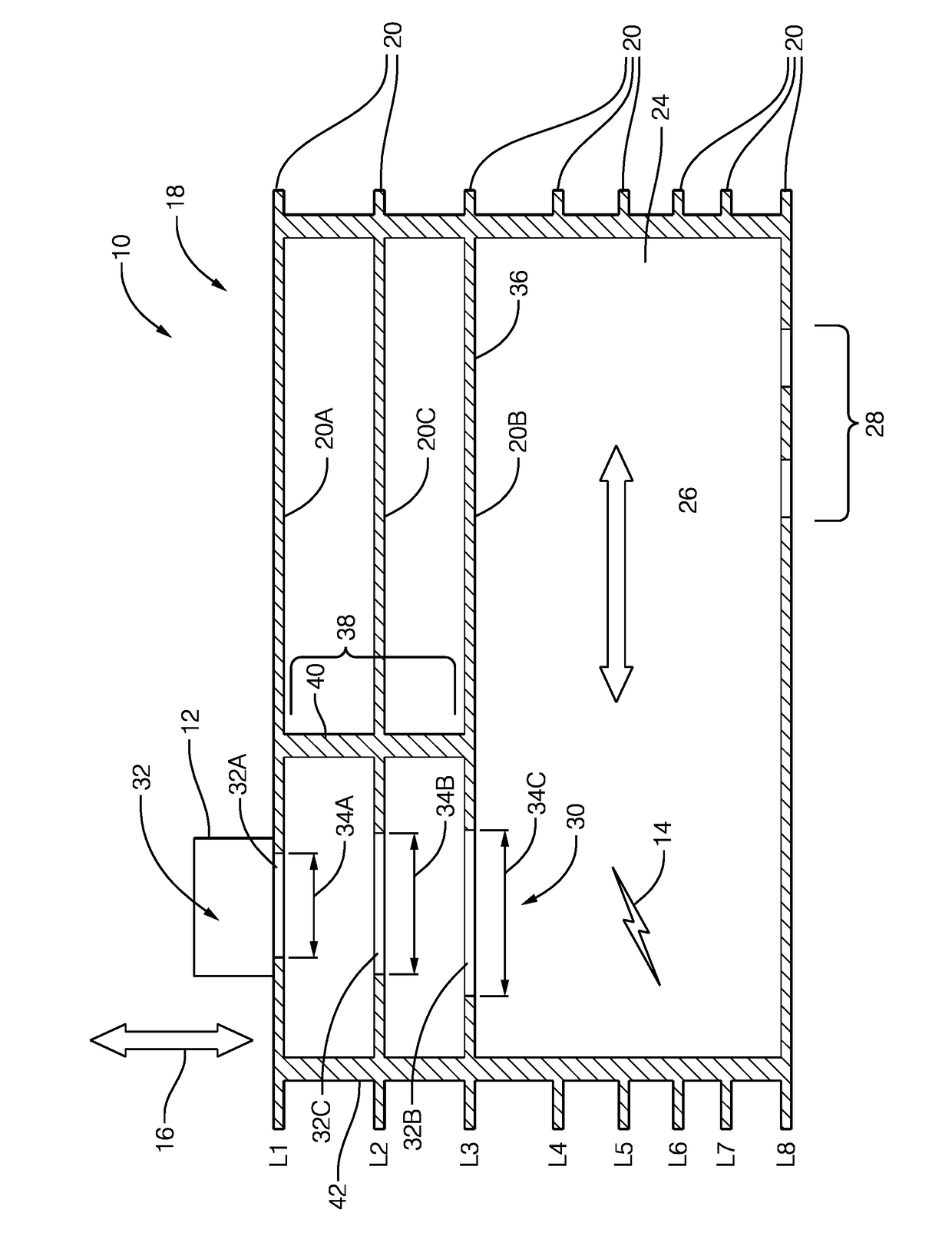
[0010]FIG. 1, FIG. 2, and FIG. 3 cooperate to illustrate a non-limiting example of a radar assembly 10, hereafter referred to as the assembly 10. The assembly 10 may be part of a larger radar system (not shown), where the assembly 10 provides a transition means between different types of waveguides used to propagate electromagnetic energy in the radar system from one location to another location.

[0011]The assembly 10 includes a rectangular-waveguide 12 or RWG 12 that propagates the electromagnetic energy 14 in a traverse electric mode (TE10) and in a first direction 16. The first direction 16 is illustrated as a double-ended arrow because, as will be recognized by those in the art, the RWG 12 can be used to propagate the electromagnetic energy 14 into (i.e. towards) the assembly 10, or out of (i.e. away from) the assembly 10. The physical size of the RWG 12 is selected based on the operating frequency of the radar system using well-known design rules.

[0012]The assembly 10 also inclu...


PUM


Abstract

A radar assembly includes a rectangular-waveguide (RWG) and a printed-circuit-board. The rectangular-waveguide (RWG) propagates electromagnetic energy in a traverse electric mode (TE10) and in a first direction. The printed-circuit-board includes a plurality of conductor-layers oriented parallel to each other. The printed-circuit-board defines a substrate-integrated-waveguide (SIW) that propagates the electromagnetic energy in a traverse electric mode (TE10) and in a second direction perpendicular to the first direction, and defines a transition that propagates the electromagnetic energy between the rectangular-wave-guide and the substrate-integrated-waveguide. The transition includes apertures defined by at least three of the plurality of conductor-layers.

Description

TECHNICAL FIELD OF INVENTION[0001]This disclosure generally relates to a radar assembly, and more particularly relates to a transition between a rectangular-waveguide (RWG) and a substrate-integrated-waveguide (SIW) where the transition includes apertures defined by at least three of a plurality of conductor-layers of a printed circuit board that also defines the SIW.BACKGROUND OF INVENTION[0002]Wideband Transitions are used in wide band radar systems such as Automotive Radar. Known transitions with sufficient bandwidths include undesirably expensive waveguide flanges or metal structures, where critical tolerances add to the cost.SUMMARY OF THE INVENTION[0003]Described herein is a wideband transition that is formed using standard printed circuit board (PCB) processes, so is able to avoid using expensive waveguide flanges or metal structures. The non-limiting example described herein provides a transition between a Rectangular Waveguide (RWG) to a Substrate Integrated Waveguide (SIW)...

Claims


Application Information

Patent Timeline
IPC IPC(8): H01P3/12G01S13/02
CPCG01S13/0209H01P3/121G01S7/02H01P5/024
Inventor MANGAIAHGARI, SANKARA NARAYANA
Owner APTIV TECH LTD
Why Eureka
Try Eureka