Inspection apparatus, inspection method and storage medium

a technology of inspection apparatus and inspection method, applied in the direction of electrical apparatus, pictoral communication, etc., can solve the problems of reducing the accuracy of inspection of printed images, the appearance pattern of surfaces and the concave/convex pattern may not be exactly the same for every one,

Active Publication Date: 2018-08-09
RICOH KK
View PDF0 Cites 23 Cited by
  • Summary
  • Abstract
  • Description
  • Claims
  • Application Information

AI Technical Summary

Benefits of technology

[0007]As one aspect of the present invention, an inspection apparatus is devised. The inspection apparatus includes circuitry to acquire a first scanned image by scanning each recording media printed with a target image as a printed matter using a scanner, the printed matter including a drawing region where the target image is drawn, and a non-drawing region where the target image is not drawn, acquire a second scanned image by scanning one recording medium printed with a color chart including a plurality of color patches using the scanner without printing the target image on the one recording medium, the one recording medium and the each recording media having a similar property, generate index color information including information of a plurality of index colors having higher frequency of occurrence on the one recording medium for each of the plurality of color patches configuring the color chart printed on the one recording medium, generate color conversion information by associating a value of each of the plurality of color patches and a color value of each of the plurality of index colors included in the index color information, generate a reference image as an inspection standard for inspecting the printed matter for each of the plurality of index colors having higher frequency of occurrence by performing a color conversion of the target image by applying the color conversion information, the generated reference image including a plurality of reference images, calculate a difference of a color value of each one of pixels configuring the first scanned image and a color value of each one of pixels of each of the plurality of reference images, corresponding to each one of the pixels configuring the first scanned image, as a color difference value of each one of the pixels configuring the first scanned image, the calculated color difference value includes a plurality of color difference values, and inspect the printed matter based on the plurality of color difference values calculated for the pixels configuring the first scanned image.
[0008]As another aspect of the present invention, a method of inspecting a printed matter is devised. The method includes acquiring a first scanned image by scanning each recording media printed with a target image as a printed matter using a scanner, the printed matter including a drawing region where the target image is drawn, and a non-drawing region where the target image is not drawn, acquiring a second scanned image by scanning one recording medium printed with a color chart including a plurality of color patches using the scanner without printing the target image on the one recording medium, the one recording medium and the each recording media having a similar property, generating index color information including information of a plurality of index colors having higher frequency of occurrence on the one recording medium for each of the plurality of color patches configuring the color chart printed on the one recording medium, generating color conversion information by associating a value of each of the plurality of color patches and a color value of each of the plurality of index colors included in the index color information, generating a reference image as an inspection standard for inspecting the printed matter for each of the plurality of index colors having higher frequency of occurrence by performing a color conversion of the target image by applying the color conversion information, the generated reference image including a plurality of reference images, calculating a difference of a color value of each one of pixels configuring the first scanned image and a color value of each one of pixels of each of the plurality of reference images, corresponding to each one of the pixels configuring the first scanned image, as a color difference value of each one of the pixels configuring the first scanned image, the calculated color difference value includes a plurality of color difference values, and inspecting the printed matter based on the plurality of color difference values calculated for the pixels configuring the first scanned image.
[0009]As another aspect of the present invention, a non-transitory storage medium storing one or more instructions that, when executed by one or more processors, cause the one or more processors to execute a method of inspecting a printed matter is devised. The method includes acquiring a first scanned image by scanning each recording media printed with a target image as a printed matter using a scanner, the printed matter including a drawing region where the target image is drawn, and a non-drawing region where the target image is not drawn, acquiring a second scanned image by scanning one recording medium printed with a color chart including a plurality of color patches using the scanner without printing the target image on the one recording medium, the one recording medium and the each recording media having a similar property, generating index color information including information of a plurality of index colors having higher frequency of occurrence on the one recording medium for each of the plurality of color patches configuring the color chart printed on the one recording medium, generating color conversion information by associating a value of each of the plurality of color patches and a color value of each of the plurality of index colors included in the index color information, generating a reference image as an inspection standard for inspecting the printed matter for each of the plurality of index colors having higher frequency of occurrence by performing a color conversion of the target image by applying the color conversion information, the generated reference image including a plurality of reference images, calculating a difference of a color value of each one of pixels configuring the first scanned image and a color value of each one of pixels of each of the plurality of reference images, corresponding to each one of the pixels configuring the first scanned image, as a color difference value of each one of the pixels configuring the first scanned image, the calculated color difference value includes a plurality of color difference values, and inspecting the printed matter based on the plurality of color difference values calculated for the pixels configuring the first scanned image.

Problems solved by technology

However, when the recording media have a surface pattern such as a surface appearance pattern and concave / convex pattern, the surface appearance pattern and the concave / convex pattern may not be exactly same for every one of sheets used as the recording media.
In this case, the above described assumption cannot be applied to the generated reference image, and the surface pattern of the recording media cannot be reproduced correctly for the generated reference image, with which the printed image inspection accuracy decreases.

Method used


Image

  • Inspection apparatus, inspection method and storage medium
  • Inspection apparatus, inspection method and storage medium
  • Inspection apparatus, inspection method and storage medium

Examples


first embodiment

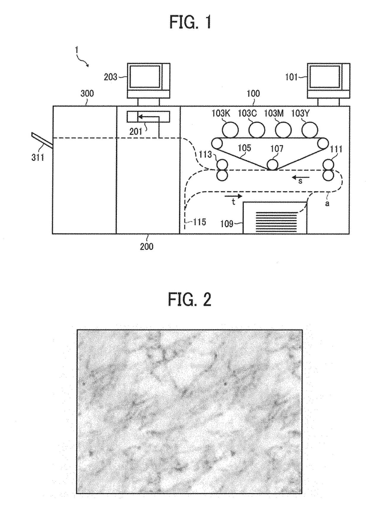
[0033]FIG. 1 illustrates an example of a schematic configuration of a printing inspection system 1 of a first embodiment. As illustrated in FIG. 1, the print inspection system 1 includes, for example, a printing apparatus 100, a print inspection apparatus 200, and a stacker 300, in which the print inspection apparatus 200 is used as one example of inspection apparatuses.

[0034]As illustrated in FIG. 1, the printing apparatus 100 includes, for example, an operation panel 101, photoconductor drums 103Y, 103M, 103C, 103K, a transfer belt 105, a secondary transfer roller 107, a sheet feed unit 109, a conveyance roller pair 111, a fixing roller 113, and an inverting path mechanism 115.

[0035]The operation panel 101 is an operation / display unit used for inputting various operations to the printing apparatus 100 and displaying various screens.

[0036]A toner image is formed on each of the photoconductor drums 103Y, 103M, 103C, 103K by performing an image forming process including a charging pr...

second embodiment

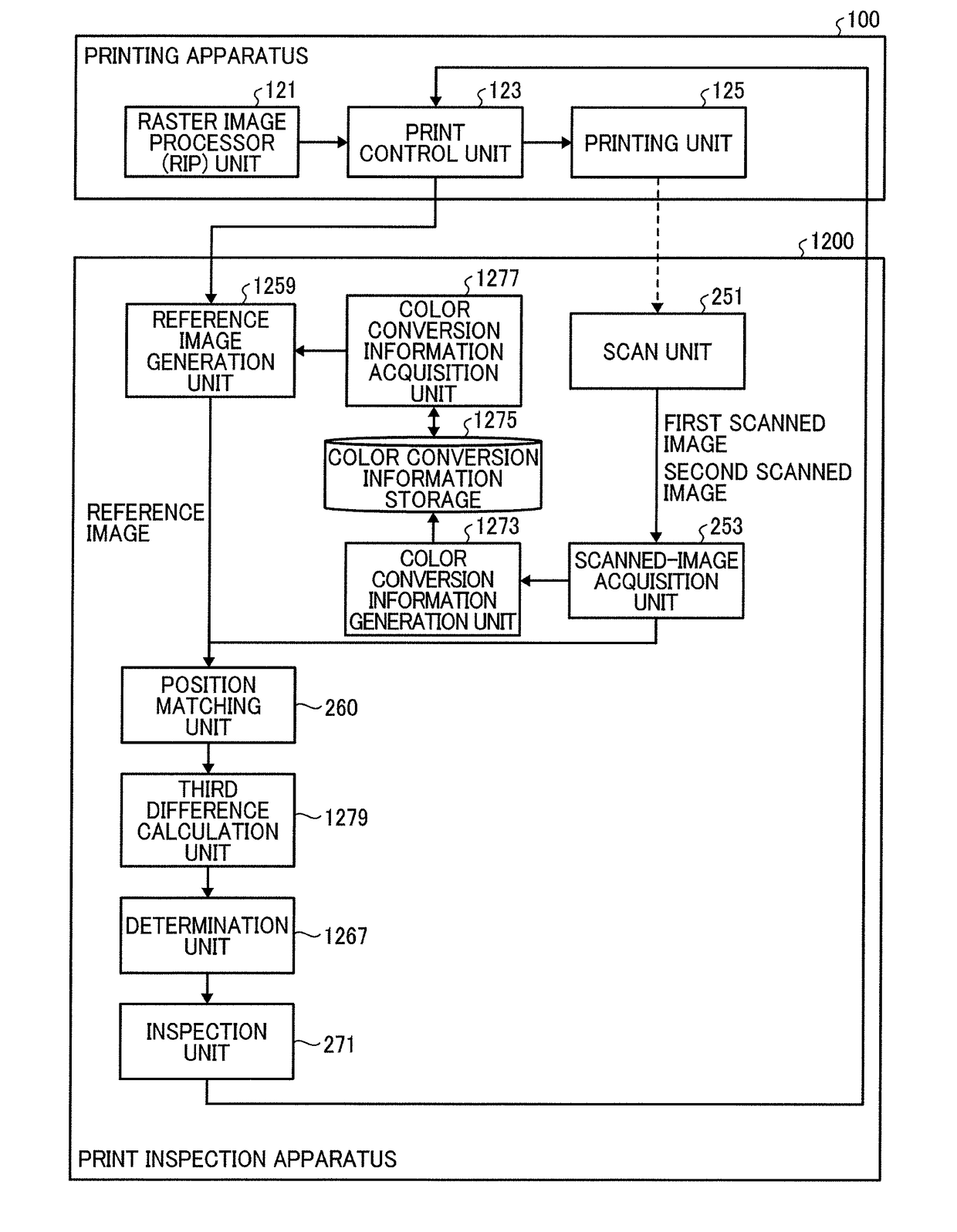
[0141]In the above described first embodiment, it is assumed that the surface pattern of the recording medium is not seen or observed through the drawing region on the printed matter. However, when an adhered amount of toner or ink is small and / or when colorant having given properties is used, the surface pattern of the recording medium may be seen through the drawing region, with which the printed image inspection accuracy may deteriorate.

[0142]In view of this issue, a description is given of a configuration to cope with a situation when the surface pattern of the recording medium is seen through the drawing region formed on the printed matter in a second embodiment. In the following description, the description of the different points from the first embodiment is mainly described, and the names and references of the second embodiment having the same functions in the first embodiment are denoted with the same names and references of the first embodiment, and thereby the description...


PUM


Abstract

An inspection apparatus includes circuitry to acquire a first scanned image by scanning each recording media printed with a target image, acquire a second scanned image by scanning one recording medium printed with a color chart including a plurality of color patches, generate index color information including information of index colors having higher frequency of occurrence on the one recording medium for each of the color patches, generate color conversion information by associating each of the color patches and each of the index colors, generate a reference image for each of the index colors by performing a color conversion of the target image by applying the color conversion information, calculate a difference of a color value of each pixel configuring the first scanned image and a color value of each pixel of each of reference images, and inspect the printed matter based on a plurality of color difference values.

Description

CROSS-REFERENCE TO RELATED APPLICATION[0001]This application claims priority pursuant to 35 U.S.C. § 119(a) to Japanese Patent Application No. 2017-020524, filed on Feb. 7, 2017 in the Japan Patent Office, the disclosure of which is incorporated by reference herein in its entirety.BACKGROUNDTechnical Field[0002]This disclosure relates to an inspection apparatus, an inspection method, and storage medium.Background Art[0003]Printing operations in production printing require the quality inspection for printed matters to achieve higher quality of the printed matters. For example, an inspection apparatus detects defects existing on a printed matter by comparing a reference image, which is a standard for inspecting the printed matter, and a scanned image generated by optically scanning the printed matter, and inspects quality of the printed matter based on a level of the detected defects.[0004]In this inspection apparatus, the reference image is generated based on an assumption that a sur...

Claims


Application Information

Patent Timeline
Patent Type & Authority Applications(United States)
IPC IPC(8): H04N1/60H04N1/00
CPCH04N1/6097H04N1/00806H04N1/6033H04N1/6072H04N2201/0082H04N2201/0005H04N1/6036H04N2201/0094
Inventor FUKASE, TAKAHIRO
Owner RICOH KK
Why Eureka
Try Eureka